Initial Installation
QUALIFIED INSTALLERS ONLY
Installation of Appliance:
1.This unit has been shipped as a
rear vented unit before installed.
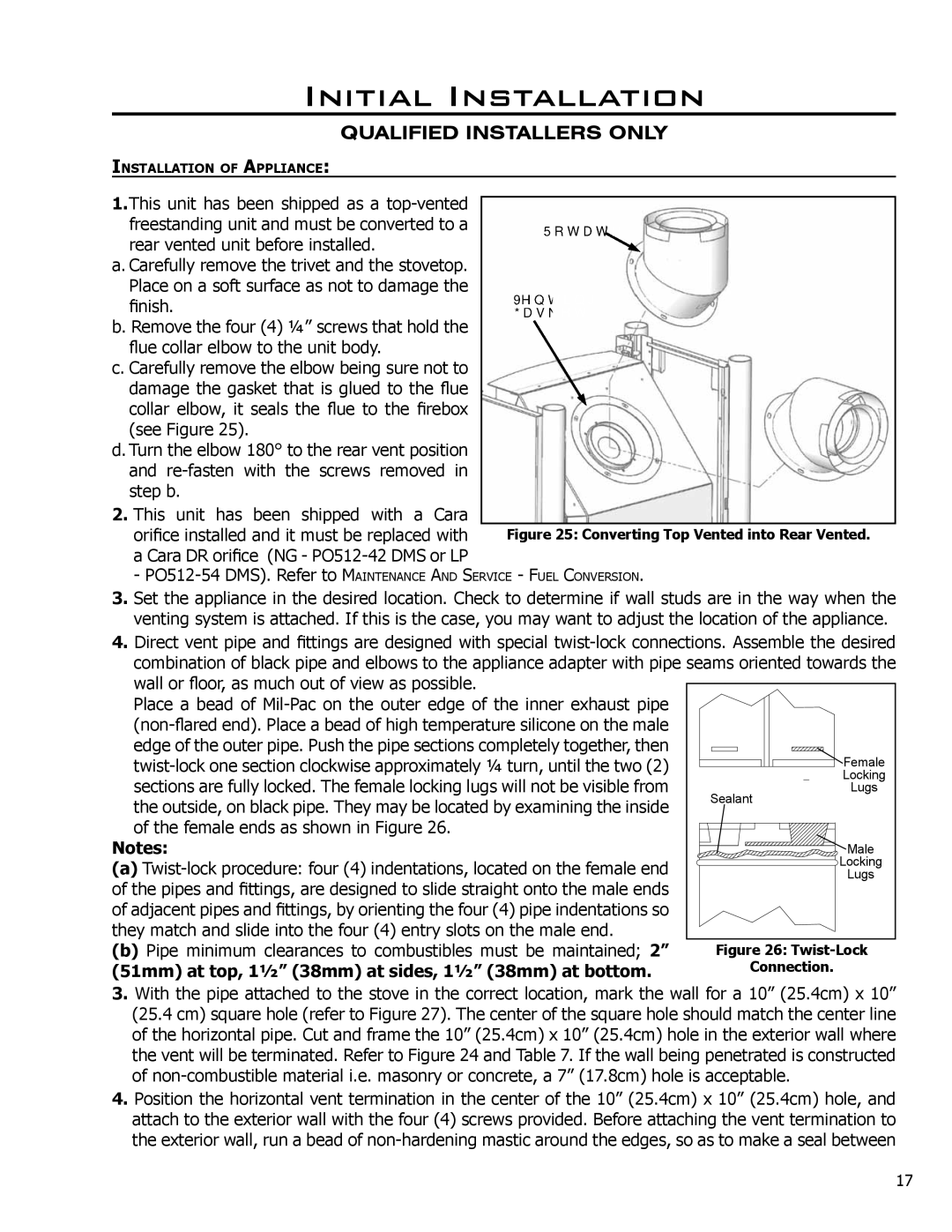
a. Carefully remove the trivet and the stovetop. Place on a soft surface as not to damage the finish.
b. Remove the four (4) ¼” screws that hold the flue collar elbow to the unit body.
c. Carefully remove the elbow being sure not to damage the gasket that is glued to the flue collar elbow, it seals the flue to the firebox (see Figure 25).
d. Turn the elbow 180° to the rear vent position and
2.This unit has been shipped with a Cara
orifice installed and it must be replaced with a Cara DR orifice (NG -
-
3.Set the appliance in the desired location. Check to determine if wall studs are in the way when the venting system is attached. If this is the case, you may want to adjust the location of the appliance.
4.Direct vent pipe and fittings are designed with special
Place a bead of |
|
|
|
|
|
|
|
|
|
|
|
|
|
|
|
|
|
|
| |
|
|
|
|
|
|
|
|
|
|
|
|
|
|
|
|
|
|
| ||
|
|
|
|
|
|
|
|
|
|
|
|
|
|
|
|
|
|
| ||
edge of the outer pipe. Push the pipe sections completely together, then |
|
|
|
|
|
|
|
|
|
|
|
|
|
|
|
|
|
| Female | |
|
|
|
|
|
|
|
|
|
|
|
|
|
|
|
|
|
| |||
|
|
|
|
|
|
|
|
|
|
|
|
|
|
|
|
|
| |||
|
|
|
|
|
|
|
|
|
|
|
|
|
|
|
|
|
| |||
|
|
|
|
|
|
|
|
|
|
|
|
|
|
|
|
|
| |||
sections are fully locked. The female locking lugs will not be visible from |
|
|
|
|
|
|
|
|
|
|
|
|
|
|
|
|
|
| Locking | |
Sealant |
|
|
|
| Lugs | |||||||||||||||
the outside, on black pipe. They may be located by examining the inside |
|
| ||||||||||||||||||
|
|
|
|
|
|
|
|
|
|
|
|
|
|
|
|
|
|
| ||
of the female ends as shown in Figure 26. |
|
|
|
|
|
|
|
|
|
|
|
|
|
|
|
|
|
|
| |
|
|
|
|
|
|
|
|
|
|
|
|
|
|
|
|
|
|
| ||
Notes: |
|
|
|
|
|
|
|
|
|
|
|
|
|
|
|
|
|
| Male | |
|
|
|
|
|
|
|
|
|
|
|
|
|
|
|
|
|
| |||
(a) |
|
|
|
|
|
|
|
|
|
|
|
|
|
|
|
|
|
| Locking | |
|
|
|
|
|
|
|
|
|
|
|
|
|
|
|
|
|
| |||
|
|
|
|
|
|
|
|
|
|
|
|
|
|
|
|
|
| |||
of the pipes and fittings, are designed to slide straight onto the male ends |
|
|
|
|
|
|
|
|
|
|
|
|
|
|
|
|
|
| Lugs | |
|
|
|
|
|
|
|
|
|
|
|
|
|
|
|
|
|
|
| ||
of adjacent pipes and fittings, by orienting the four (4) pipe indentations so |
|
|
|
|
|
|
|
|
|
|
|
|
|
|
|
|
|
|
| |
they match and slide into the four (4) entry slots on the male end. |
|
|
|
|
|
|
|
|
|
|
|
|
|
|
|
|
|
|
| |
|
|
|
|
|
|
|
|
|
|
|
|
|
|
|
|
|
|
| ||
|
|
|
|
|
|
|
|
|
|
|
|
|
|
|
|
|
|
| ||
(b) Pipe minimum clearances to combustibles must be maintained; 2” |
|
| Figure 26: | |||||||||||||||||
(51mm) at top, 1½” (38mm) at sides, 1½” (38mm) at bottom. |
|
|
| Connection. | ||||||||||||||||
3.With the pipe attached to the stove in the correct location, mark the wall for a 10” (25.4cm) x 10” (25.4 cm) square hole (refer to Figure 27). The center of the square hole should match the center line of the horizontal pipe. Cut and frame the 10” (25.4cm) x 10” (25.4cm) hole in the exterior wall where the vent will be terminated. Refer to Figure 24 and Table 7. If the wall being penetrated is constructed of
4.Position the horizontal vent termination in the center of the 10” (25.4cm) x 10” (25.4cm) hole, and attach to the exterior wall with the four (4) screws provided. Before attaching the vent termination to the exterior wall, run a bead of
17