English
![]() CAUTION: Wear appropriate personal hearing pro- tection during use. Under some conditions and duration of use, noise from this product may contribute to hearing loss.
CAUTION: Wear appropriate personal hearing pro- tection during use. Under some conditions and duration of use, noise from this product may contribute to hearing loss. ![]() WARNING: Some dust created by power sanding, sawing, grinding, drilling, and other construction activities contains chemicals known to cause cancer, birth defects or other reproductive harm. Some examples of these chemicals are:
WARNING: Some dust created by power sanding, sawing, grinding, drilling, and other construction activities contains chemicals known to cause cancer, birth defects or other reproductive harm. Some examples of these chemicals are:
•lead from
•crystalline silica from bricks and cement and other masonry products.
•arsenic and chromium from
Your risk from these exposures varies, depending on how often you do this type of work. To reduce your exposure to these chemicals: work in a well ventilated area, and work with approved safety equipment, such as those dust masks that are specially designed to filter out microscopic particles.
•Avoid prolonged contact with dust from power sand- ing, sawing, grinding, drilling, and other construction activities. Wear protective clothing and wash exposed areas with soap and water. Allowing dust to get into your mouth, eyes, or lay on the skin may promote absorption of harmful chemicals.
![]() CAUTION: A dust mask or respirator should be worn by all persons entering the work area. The filter should be replaced daily or whenever the wearer has difficulty breath- ing. See your local hardware store for the proper NIOSH/OSHA approved dust mask.
CAUTION: A dust mask or respirator should be worn by all persons entering the work area. The filter should be replaced daily or whenever the wearer has difficulty breath- ing. See your local hardware store for the proper NIOSH/OSHA approved dust mask.
• The label on your tool may include the following symbols. The symbols and their definitions are as follows:
V | volts | A | amperes | |||
Hz | hertz | W | watts | |||
min | ......minutes | no | ....alternating current | |||
|
| ....direct current | no load speed | |||
|
| |||||
|
| Class II Construction |
|
| earthing terminal | |
| ........ |
| ...... | |||
|
|
|
| |||
|
|
|
| |||
| ........ | safety alert symbol | .../min revolutions per | |||
Specifications | ..........minute | |||||
|
|
| ||||
| Input | 120V AC, 15 Amp | ||||
| 10,000 RPM | |||||
| Feed speed | 26 ft. per minute | ||||
| Planing height | Maximum 6", Minimum 1/8" | ||||
| Planing width | Maximum | ||||
| Planing depth | Maximum 1/8" | ||||
|
|
| (for boards 6" wide or less) | |||
Electrical Connection
Be sure your power supply agrees with the nameplate mark- ing. Volts, 50/60 Hz or “AC only” means your planer must be operated only with alternating current and never with direct current. Voltage decrease of more than 10% will cause loss of power and overheating. All DeWalt tools are factory test- ed, if this tool does not operate, check the power supply.
Unpacking Your Planer
Check the contents of your planer carton to make sure you have received all parts. In addition to this instruction manu- al, the carton should contain:
•1 Planer
•1 Depth Adjustment Crank Handle
•1 Allen Screw for Crank Handle
•1 Dust Hood
•1 Crescent Wrench
•1
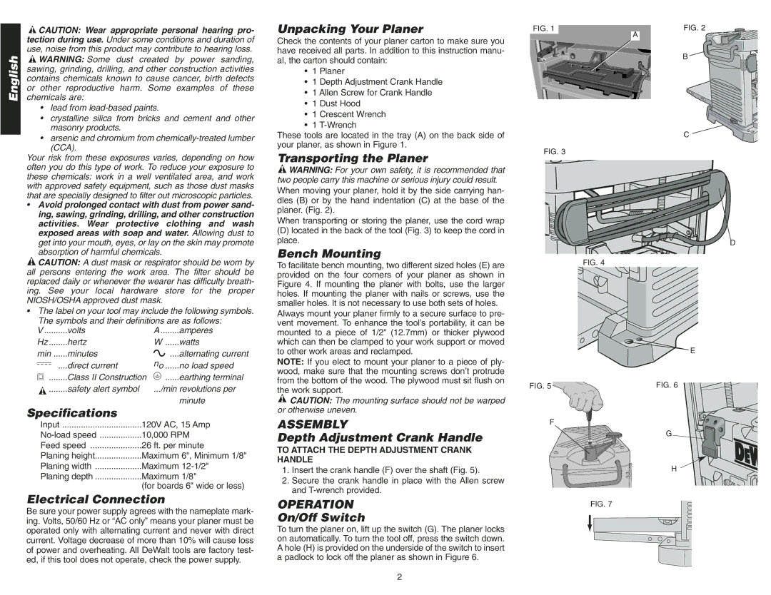
These tools are located in the tray (A) on the back side of your planer, as shown in Figure 1.
Transporting the Planer
![]() WARNING: For your own safety, it is recommended that two people carry this machine or serious injury could result. When moving your planer, hold it by the side carrying han- dles (B) or by the hand indentation (C) at the base of the planer. (Fig. 2).
WARNING: For your own safety, it is recommended that two people carry this machine or serious injury could result. When moving your planer, hold it by the side carrying han- dles (B) or by the hand indentation (C) at the base of the planer. (Fig. 2).
When transporting or storing the planer, use the cord wrap
(D)located in the back of the tool (Fig. 3) to keep the cord in place.
Bench Mounting
To facilitate bench mounting, two different sized holes (E) are provided on the four corners of your planer as shown in Figure 4. If mounting the planer with bolts, use the larger holes. If mounting the planer with nails or screws, use the smaller holes. It is not necessary to use both sets of holes.
Always mount your planer firmly to a secure surface to pre- vent movement. To enhance the tool’s portability, it can be mounted to a piece of 1/2" (12.7mm) or thicker plywood which can then be clamped to your work support or moved to other work areas and reclamped.
NOTE: If you elect to mount your planer to a piece of ply- wood, make sure that the mounting screws don’t protrude from the bottom of the wood. The plywood must sit flush on the work support.
![]() CAUTION: The mounting surface should not be warped or otherwise uneven.
CAUTION: The mounting surface should not be warped or otherwise uneven.
ASSEMBLY
Depth Adjustment Crank Handle
TO ATTACH THE DEPTH ADJUSTMENT CRANK HANDLE
1.Insert the crank handle (F) over the shaft (Fig. 5).
2.Secure the crank handle in place with the Allen screw and
OPERATION
On/Off Switch
To turn the planer on, lift up the switch (G). The planer locks on automatically. To turn the tool off, press the switch down. A hole (H) is provided on the underside of the switch to insert a padlock to lock off the planer as shown in Figure 6.
FIG. 1 | FIG. 2 |
| A |
| B |
C
FIG. 3
D
FIG. 4
E
FIG. 5 | FIG. 6 |
F
G
H
FIG. 7
2