SPECIFICATIONS |
|
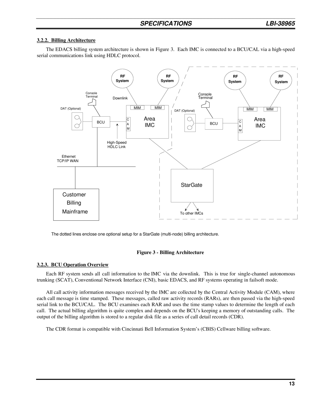
3.2.2. Billing Architecture
The EDACS billing system architecture is shown in Figure 3. Each IMC is connected to a BCU/CAL via a
RF | RF |
System | System |
RF | RF |
System | System |
Console
TerminalDownlink
|
|
|
|
|
|
|
|
|
|
|
|
|
|
|
|
DAT (Optional) | MIM |
| MIM |
| |||
BCU | C | Area | |
A | IMC | ||
| |||
| M | ||
|
| ||
|
| ||
| HDLC Link |
| |
Ethernet |
|
| |
TCP/IP WAN |
|
|
Console
Terminal
DAT (Optional)
BCU
| MIM |
| MIM |
|
CArea
AIMC
M
StarGate
Customer
Billing
Mainframe | To other IMCs |
The dotted lines enclose one optional setup for a StarGate
Figure 3 - Billing Architecture
3.2.3. BCU Operation Overview
Each RF system sends all call information to the IMC via the downlink. This is true for
All call activity information messages received by the IMC are collected by the Central Activity Module (CAM), where each call message is time stamped. These messages, called raw activity records (RARs), are then passed via the
The CDR format is compatible with Cincinnati Bell Information System’s (CBIS) Cellware billing software.
13