EDACS BILLING FORMAT |
|
The following table defines the ASCII characters used in the CDR
CDR Radix-64 Digit
![]()
![]() 0123456789
0123456789
![]()
![]() ABCDEFGHIJ
ABCDEFGHIJ
![]()
![]() KLMNOPQRST
KLMNOPQRST
![]()
![]() UVWXYZabcd
UVWXYZabcd
![]()
![]() efghijklmn
efghijklmn
![]()
![]() opqrstuvwx
opqrstuvwx
![]()
![]() yz#$
yz#$
5. RECORD LAYOUT
5.1. SINGLE-SITE CALLS
Decimal Equivalent
0 to 9
10 to 19
20 to 29
30 to 39
40 to 49
50 to 59
60 to 63
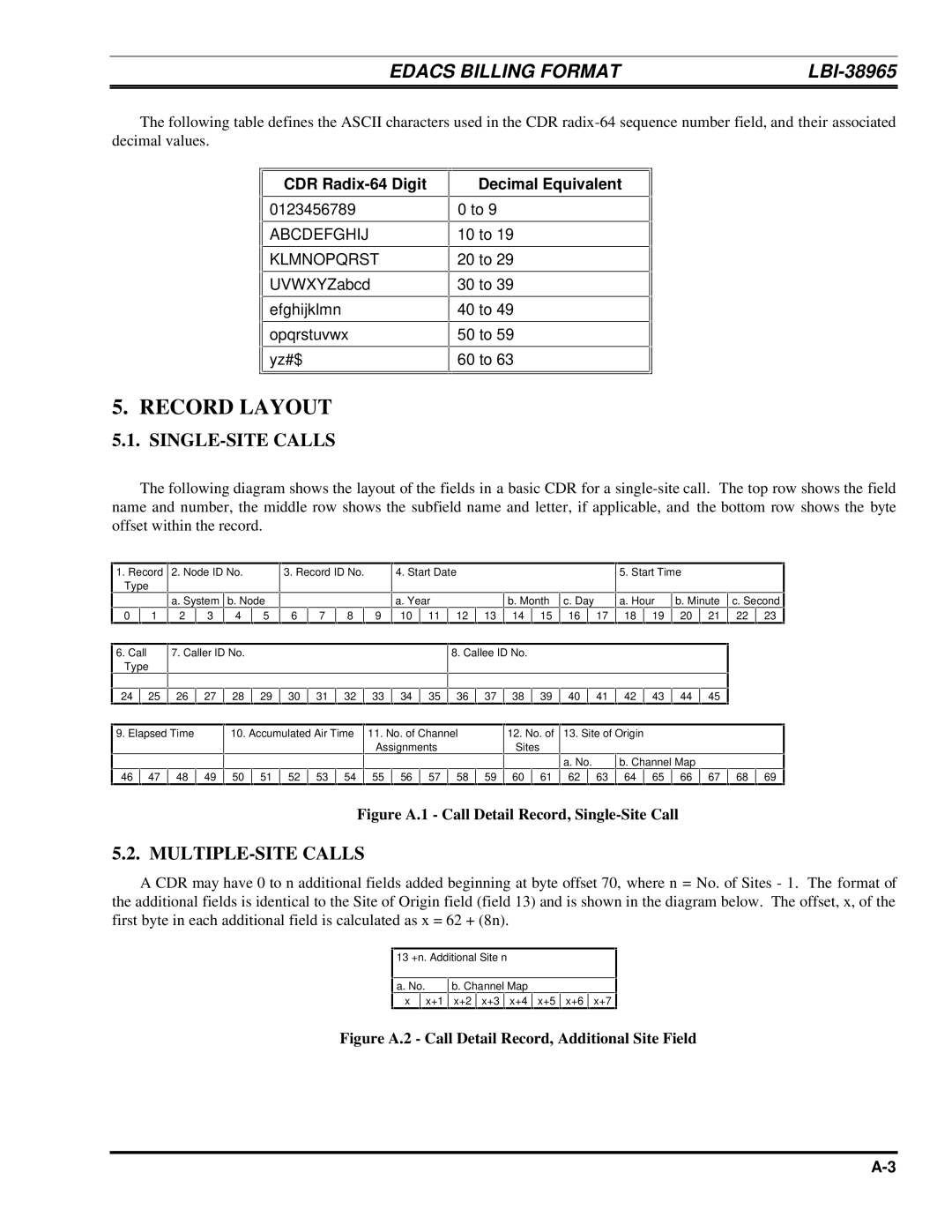
The following diagram shows the layout of the fields in a basic CDR for a
1.Record 2. Node ID No. Type
|
| a. System | b. Node | ||
0 | 1 | 2 | 3 | 4 | 5 |
3. Record ID No.
6 | 7 | 8 | 9 |
4. Start Date |
|
|
|
|
|
| 5. Start Time |
|
|
| ||||
|
|
|
|
|
|
|
|
|
|
|
|
|
|
|
a. Year |
|
| b. Month | c. Day |
| a. Hour | b. Minute | c. Second | ||||||
10 | 11 | 12 | 13 | 14 | 15 | 16 |
| 17 | 18 | 19 | 20 | 21 | 22 | 23 |
6.Call Type
7. Caller ID No.
8. Callee ID No.
24 | 25 | 26 | 27 | 28 | 29 | 30 | 31 | 32 | 33 | 34 | 35 | 36 | 37 | 38 | 39 | 40 | 41 | 42 | 43 | 44 | 45 |
9. Elapsed Time
10. Accumulated Air Time 11. No. of Channel Assignments
12. No. of 13. Site of Origin Sites
|
|
|
|
|
|
|
|
|
|
|
|
|
|
|
| a. No. |
| b. Channel Map |
|
|
| |||
46 | 47 | 48 | 49 | 50 | 51 | 52 | 53 | 54 | 55 | 56 | 57 | 58 | 59 | 60 | 61 | 62 |
| 63 | 64 | 65 | 66 | 67 | 68 | 69 |
Figure A.1 - Call Detail Record, Single-Site Call
5.2. MULTIPLE-SITE CALLS
A CDR may have 0 to n additional fields added beginning at byte offset 70, where n = No. of Sites - 1. The format of the additional fields is identical to the Site of Origin field (field 13) and is shown in the diagram below. The offset, x, of the first byte in each additional field is calculated as x = 62 + (8n).
13 +n. Additional Site n |
|
|
|
| |||||
|
|
|
|
|
|
|
|
| |
a. No. |
| b. Channel Map |
|
|
| ||||
x |
| x+1 | x+2 | x+3 |
| x+4 | x+5 | x+6 | x+7 |