Section 4 - Preparation
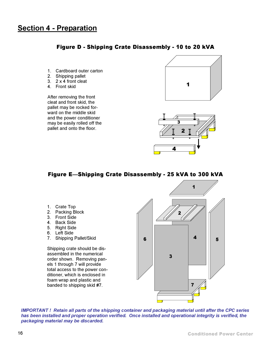
Figure D - Shipping Crate Disassembly - 10 to 20 kVA
1.Cardboard outer carton
2.Shipping pallet
3.2 x 4 front cleat
4.Front skid
After removing the front cleat and front skid, the pallet may be rocked for- ward on the middle skid and the power conditioner may be easily rolled off the pallet and onto the floor.
1
3
2
4
Figure E—Shipping Crate Disassembly - 25 kVA to 300 kVA
1.Crate Top
2.Packing Block
3.Front Side
4.Back Side
5.Right Side
6.Left Side
7.Shipping Pallet/Skid
Shipping crate should be dis- assembled in the numerical order shown. Removing pan- els 1 through 7 will provide total access to the power con- ditioner, which is enclosed in foam wrap and plastic and banded to shipping skid #7.
6
1 |
|
2 |
|
4 | 5 |
| |
3 |
|
7 |
|
IMPORTANT ! Retain all parts of the shipping container and packaging material until after the CPC series has been installed and proper operation verified. Once installed and operational integrity is verified, the packaging material may be discarded.
16 | Conditioned Power Center |
