Section 7 - Options
7.4 Phase Loss/Low Voltage Detection and Protection
When equipped with the power management option, the 7500 ION monitor also provides:
1.Protection from the loss of one or more input phases
2.Protection for a
Should a phase loss or low voltage occur, the 7500 ION will “shunt” trip the power conditioner breaker within 50 msec. of the occurrence. In this event, turn off the load. Then
NOTE: Any phase that drops below 80% of nominal voltage is considered a “phase loss” condition. The 7500 Ion monitor is powered from phase A of the transformer secondary. If the 7500 Ion monitor appears to have no power, this is an indication that phase A may be lost. Caution should be exercised, however, as phases B and C may be still be energized.
7.5 External EMO
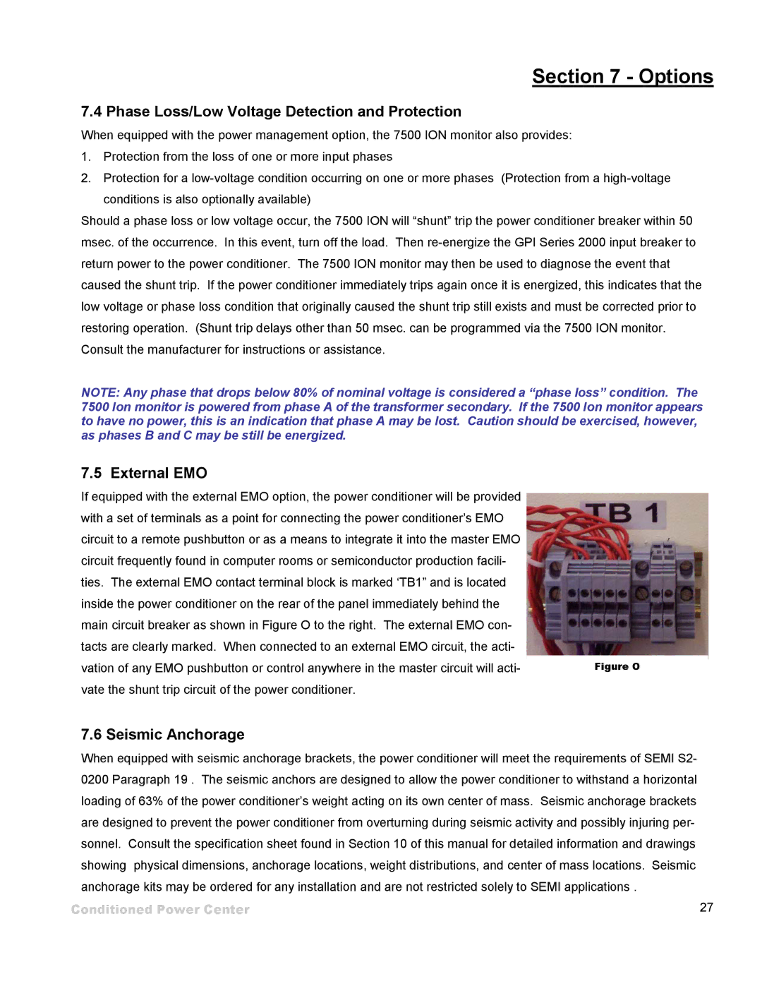
If equipped with the external EMO option, the power conditioner will be provided with a set of terminals as a point for connecting the power conditioner’s EMO circuit to a remote pushbutton or as a means to integrate it into the master EMO circuit frequently found in computer rooms or semiconductor production facili- ties. The external EMO contact terminal block is marked ‘TB1” and is located inside the power conditioner on the rear of the panel immediately behind the main circuit breaker as shown in Figure O to the right. The external EMO con- tacts are clearly marked. When connected to an external EMO circuit, the acti-
vation of any EMO pushbutton or control anywhere in the master circuit will acti-Figure O vate the shunt trip circuit of the power conditioner.
7.6 Seismic Anchorage
When equipped with seismic anchorage brackets, the power conditioner will meet the requirements of SEMI S2- 0200 Paragraph 19 . The seismic anchors are designed to allow the power conditioner to withstand a horizontal loading of 63% of the power conditioner’s weight acting on its own center of mass. Seismic anchorage brackets are designed to prevent the power conditioner from overturning during seismic activity and possibly injuring per- sonnel. Consult the specification sheet found in Section 10 of this manual for detailed information and drawings showing physical dimensions, anchorage locations, weight distributions, and center of mass locations. Seismic anchorage kits may be ordered for any installation and are not restricted solely to SEMI applications .
Conditioned Power Center | 27 |