Section 8 - Troubleshooting/Maintenance
![]() Prior to performing maintenance of any kind, lockout and tagout the electrical
Prior to performing maintenance of any kind, lockout and tagout the electrical
![]()
![]()
![]() power at both the facility source and the input circuit breaker. Under these condi-
power at both the facility source and the input circuit breaker. Under these condi- ![]() tions, entering the equipment enclosure will be classified as a Type 1 task under
tions, entering the equipment enclosure will be classified as a Type 1 task under
SEMI
8.1.2.3EMO Has Been Activated - The front panel EMO pushbutton latches in a closed position once it has been depressed. Ensure that the EMO button has not been depressed by turning the button in the direction of the arrows and allowing it to spring back to its normal operating position. If the power conditioner is equipped with the external EMO option, further ensure that remote EMO buttons or connected external EMO circuits have not been activated. Once all EMO buttons and circuits have been verified, rotate the circuit breaker handle to the extreme
8.1.2.4Safety Interlocks Activated - Check both side panels of the power conditioner for proper instal- lation and secure fit. Both panels must be firmly in place and securely fastened with the quarter turn fasteners provided. A loose or improperly attached panel will allow the safety interlocks to activate and shunt trip the front panel circuit breaker. Once the panels have been checked, rotate the circuit breaker handle to the extreme
If the circuit breaker once again trips immediately, contact the manufac- turer for further instructions.
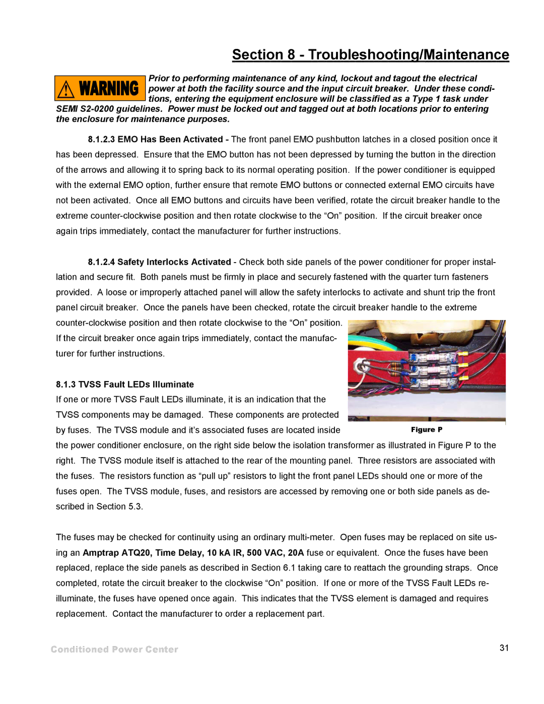
8.1.3TVSS Fault LEDs Illuminate
If one or more TVSS Fault LEDs illuminate, it is an indication that the TVSS components may be damaged. These components are protected by fuses. The TVSS module and it’s associated fuses are located inside
the power conditioner enclosure, on the right side below the isolation transformer as illustrated in Figure P to the right. The TVSS module itself is attached to the rear of the mounting panel. Three resistors are associated with the fuses. The resistors function as “pull up” resistors to light the front panel LEDs should one or more of the fuses open. The TVSS module, fuses, and resistors are accessed by removing one or both side panels as de- scribed in Section 5.3.
The fuses may be checked for continuity using an ordinary
Conditioned Power Center | 31 |