Section 5 - Installation
Transformers are designed to meet a variety of requirements. Some locations (Europe, for example) have standardized on a single input voltage. In other cases customers may specify multiple input voltages to accommodate the variety of voltages commonly found in the United States. The CPC series conditioner can accommodate either style of transformer - single voltage or multiple voltage primary.
The conditioner is a
The secondary configuration of the transformer is a five wire wye requiring three phase conductors, a neutral, and a safety ground.
5.6.1 Transformer Primary Voltage Adjustment
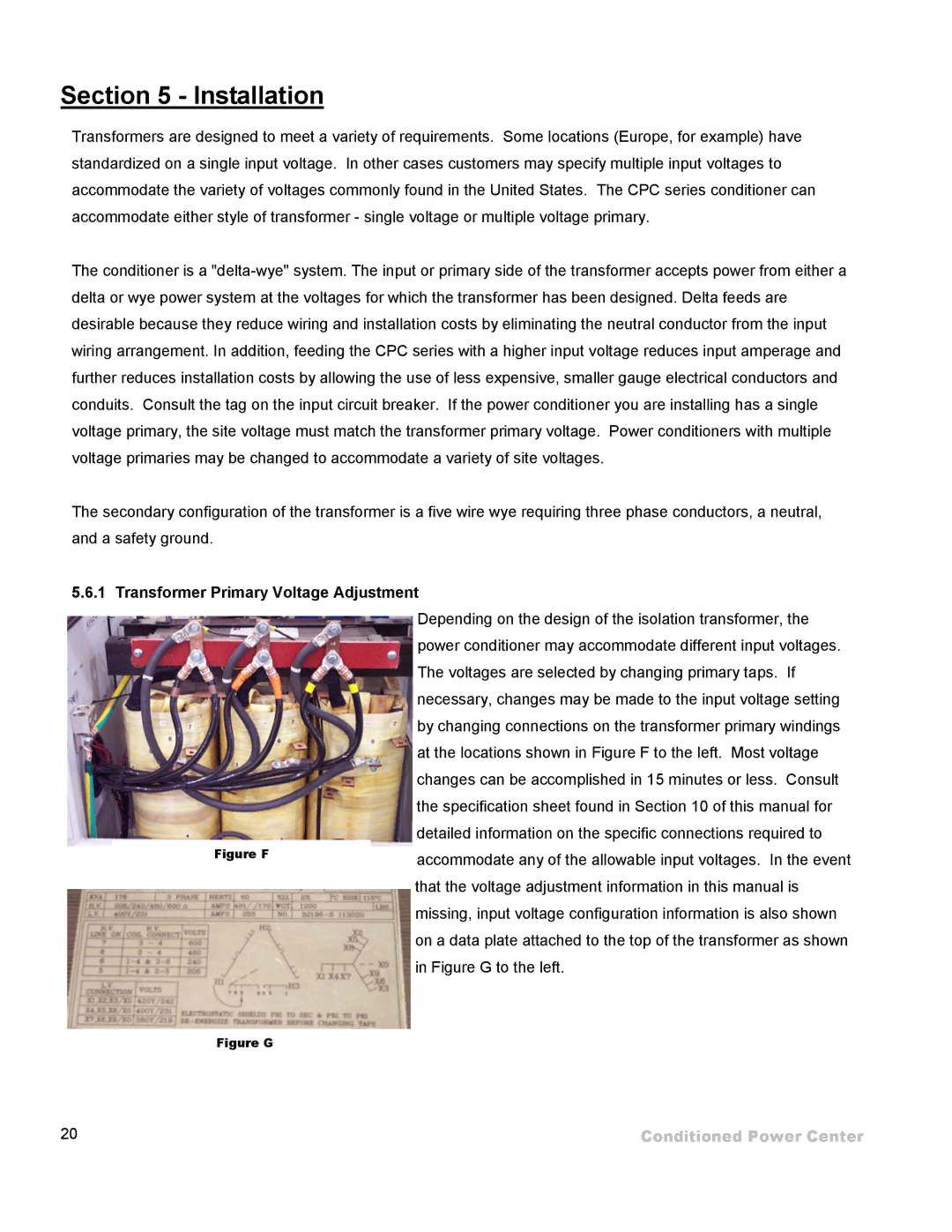
Depending on the design of the isolation transformer, the power conditioner may accommodate different input voltages. The voltages are selected by changing primary taps. If necessary, changes may be made to the input voltage setting by changing connections on the transformer primary windings at the locations shown in Figure F to the left. Most voltage changes can be accomplished in 15 minutes or less. Consult the specification sheet found in Section 10 of this manual for
detailed information on the specific connections required to
Figure Faccommodate any of the allowable input voltages. In the event that the voltage adjustment information in this manual is missing, input voltage configuration information is also shown on a data plate attached to the top of the transformer as shown in Figure G to the left.
Figure G
20 | Conditioned Power Center |