Section 5 - Installation
Specific locations for connecting the input and output safety ground conductors are discussed in Sections 5.9 and
5.10that follow. These sections cover the information necessary to connect electrical wiring to both the main and to the load. Please review both sections carefully before beginning the actual electrical installation. A sophisticated electronic system will benefit greatly when all parts of the system and all system peripherals are powered from a single power source. It is recommended that all parts of the system share this common power source and its common, "clean" ground.
![]() Connecting input wiring to the main source of power may require working inside
Connecting input wiring to the main source of power may require working inside
![]()
![]()
![]()
![]() switchgear or distribution panelboards containing live voltages. Contact with live
switchgear or distribution panelboards containing live voltages. Contact with live ![]() voltages will result in injury or death. Working inside live switchgear is classified
voltages will result in injury or death. Working inside live switchgear is classified
as a Type 4 Task under SEMI
Strict compliance with the following lockout/tagout procedure for the CPC series is ![]()
![]()
![]() required to assure personnel safety when making input and output power
required to assure personnel safety when making input and output power
![]() connections. Working inside the power conditioner with the lockout/tagout engaged may be classified by SEMI
connections. Working inside the power conditioner with the lockout/tagout engaged may be classified by SEMI
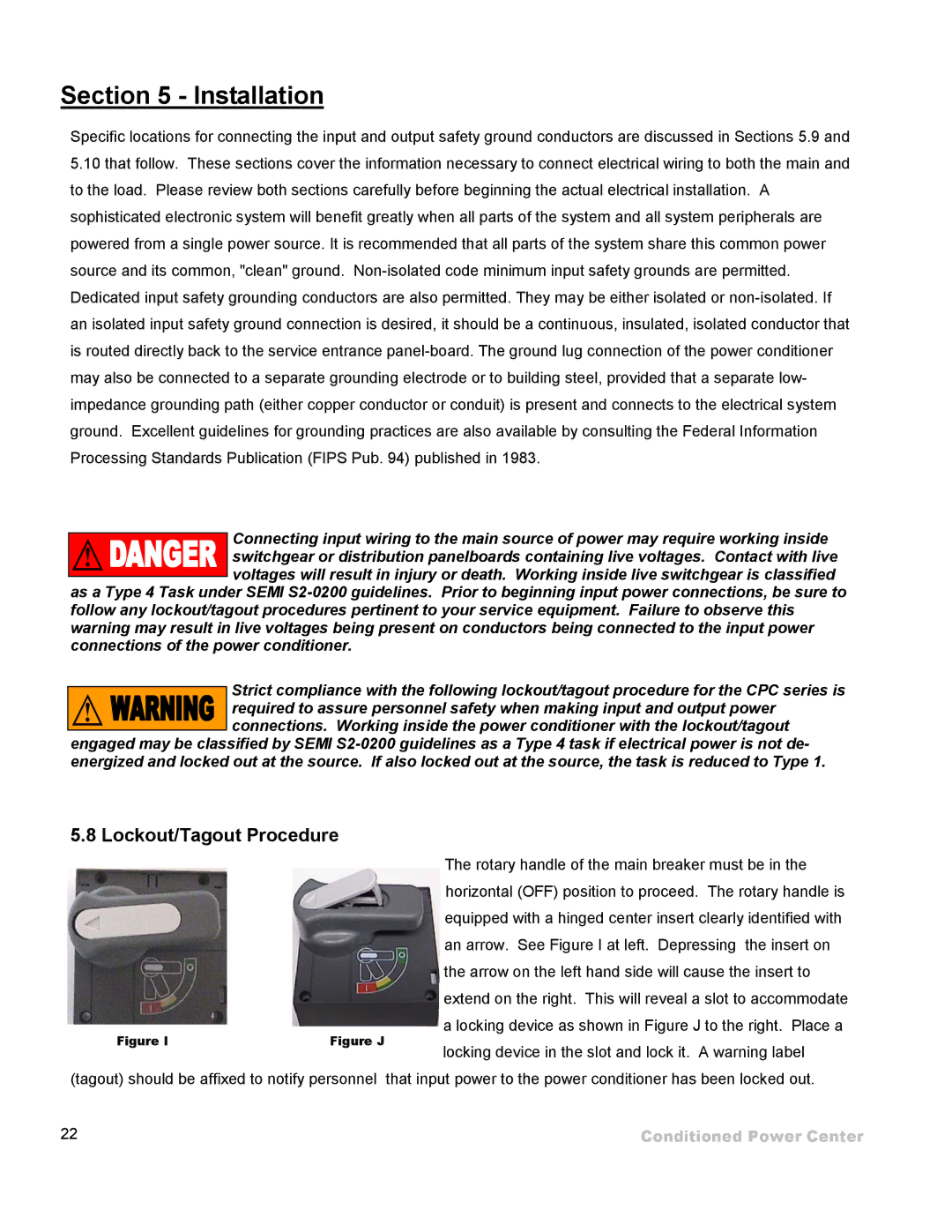
5.8 Lockout/Tagout Procedure
|
| The rotary handle of the main breaker must be in the | |
|
| horizontal (OFF) position to proceed. The rotary handle is | |
|
| equipped with a hinged center insert clearly identified with | |
|
| an arrow. See Figure I at left. Depressing the insert on | |
|
| the arrow on the left hand side will cause the insert to | |
|
| extend on the right. This will reveal a slot to accommodate | |
Figure I | Figure J | a locking device as shown in Figure J to the right. Place a | |
locking device in the slot and lock it. A warning label | |||
|
| ||
(tagout) should be affixed to notify personnel | that input power to the power conditioner has been locked out. | ||
22 |
| Conditioned Power Center | |