1.3.2. EPTZ3100/EPTZ3100I Base Board
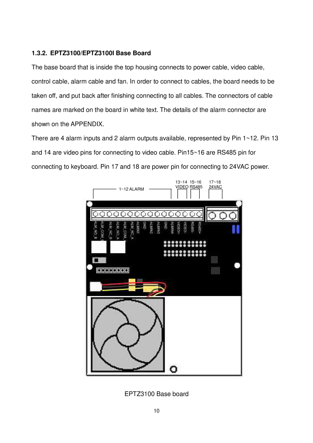
The base board that is inside the top housing connects to power cable, video cable, control cable, alarm cable and fan. In order to connect to cables, the board needs to be taken off, and put back after finishing connecting to all cables. The connectors of cable names are marked on the board in white text. The details of the alarm connector are shown on the APPENDIX.
There are 4 alarm inputs and 2 alarm outputs available, represented by Pin 1~12. Pin 13 and 14 are video pins for connecting to video cable. Pin15~16 are RS485 pin for connecting to keyboard. Pin 17 and 18 are power pin for connecting to 24VAC power.
|
| 13~14 | 15~16 | 17~18 | |||
1~12 ALARM |
| VIDEO RS485 | 24VAC | ||||
|
|
|
|
|
|
| |
|
|
|
|
|
|
|
|
EPTZ3100 Base board
10
