APPENDIX A
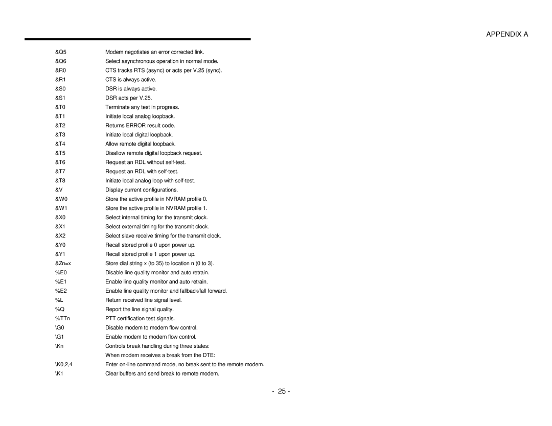
&Q5 | Modem negotiates an error corrected link. |
&Q6 | Select asynchronous operation in normal mode. |
&R0 | CTS tracks RTS (async) or acts per V.25 (sync). |
&R1 | CTS is always active. |
&S0 | DSR is always active. |
&S1 | DSR acts per V.25. |
&T0 | Terminate any test in progress. |
&T1 | Initiate local analog loopback. |
&T2 | Returns ERROR result code. |
&T3 | Initiate local digital loopback. |
&T4 | Allow remote digital loopback. |
&T5 | Disallow remote digital loopback request. |
&T6 | Request an RDL without |
&T7 | Request an RDL with |
&T8 | Initiate local analog loop with |
&V | Display current configurations. |
&W0 | Store the active profile in NVRAM profile 0. |
&W1 | Store the active profile in NVRAM profile 1. |
&X0 | Select internal timing for the transmit clock. |
&X1 | Select external timing for the transmit clock. |
&X2 | Select slave receive timing for the transmit clock. |
&Y0 | Recall stored profile 0 upon power up. |
&Y1 | Recall stored profile 1 upon power up. |
&Zn=x | Store dial string x (to 35) to location n (0 to 3). |
%E0 | Disable line quality monitor and auto retrain. |
%E1 | Enable line quality monitor and auto retrain. |
%E2 | Enable line quality monitor and fallback/fall forward. |
%L | Return received line signal level. |
%Q | Report the line signal quality. |
%TTn | PTT certification test signals. |
\G0 | Disable modem to modem flow control. |
\G1 | Enable modem to modem flow control. |
\Kn | Controls break handling during three states: |
| When modem receives a break from the DTE: |
\K0,2,4 | Enter |
\K1 | Clear buffers and send break to remote modem. |
- 25 -