325 specifications
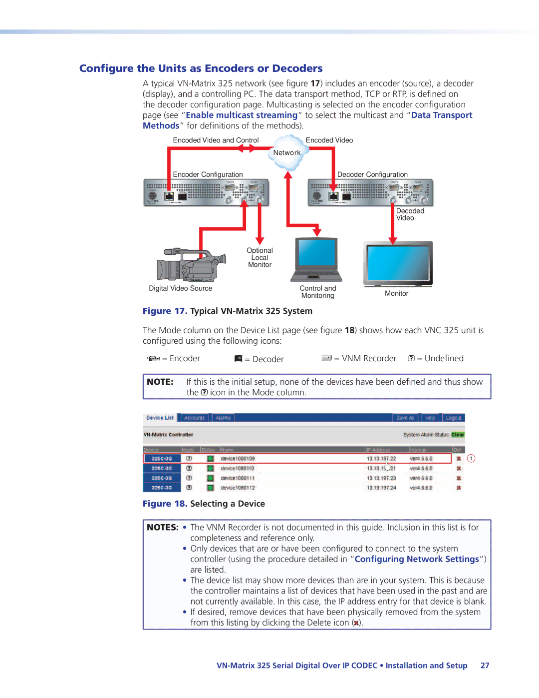
Extron Electronics has established itself as a key player in the AV technology industry, providing innovative solutions for a wide range of applications. Among their product lineup, the Extron Electronics 225 and 325 series of devices stand out for their advanced features, technologies, and characteristics that cater to both commercial and educational environments.The Extron 225 and 325 series are designed for seamless integration into various AV systems, offering unparalleled performance and reliability. At the core of these devices is their robust signal processing capability. Both models are equipped with high-performance scalers and switchers that ensure optimal video quality. They support a wide range of resolutions, including 4K, enabling users to connect various sources without compromising image fidelity.
One of the key features of the 225 and 325 series is their versatile connectivity options. These devices come with multiple inputs, including HDMI, VGA, and composite, allowing for the integration of various AV sources. The series also includes configurable outputs, which can be customized according to the specific requirements of the installation. This flexibility is vital in multipurpose spaces where different AV setups are needed.
The technologies embedded in the 225 and 325 series also enhance usability and control. They feature Extron’s integrated control systems, which simplify the operation of entire AV systems. Users benefit from the intuitive user interface, enabling easy switching and management of devices. Additionally, compatibility with third-party control systems allows for seamless integration into existing setups, streamlining operations.
Another noteworthy characteristic is the series’ built-in audio processing capabilities. Both the 225 and 325 models support various audio formats, ensuring high-quality sound output. They also include audio embedding and de-embedding functions, facilitating the integration of audio sources with video signals.
Reliability and durability are hallmarks of the Extron brand, and the 225 and 325 series are no exceptions. Designed for long-term use, these devices undergo rigorous testing to ensure they perform consistently under demanding conditions. Their compact form factor also allows for easy installation in constrained spaces, making them ideal for a variety of environments.
In summary, the Extron Electronics 225 and 325 series deliver top-tier performance, expansive connectivity, and exceptional audio-visual processing capabilities. Their innovative features and robust design make them valuable additions to any AV installation, catering to a wide range of user needs in commercial and educational settings. With Extron’s commitment to quality and user-friendly solutions, the 225 and 325 series stand as testament to their leadership in the AV technology realm.

