Installation
Step 6: AAPs
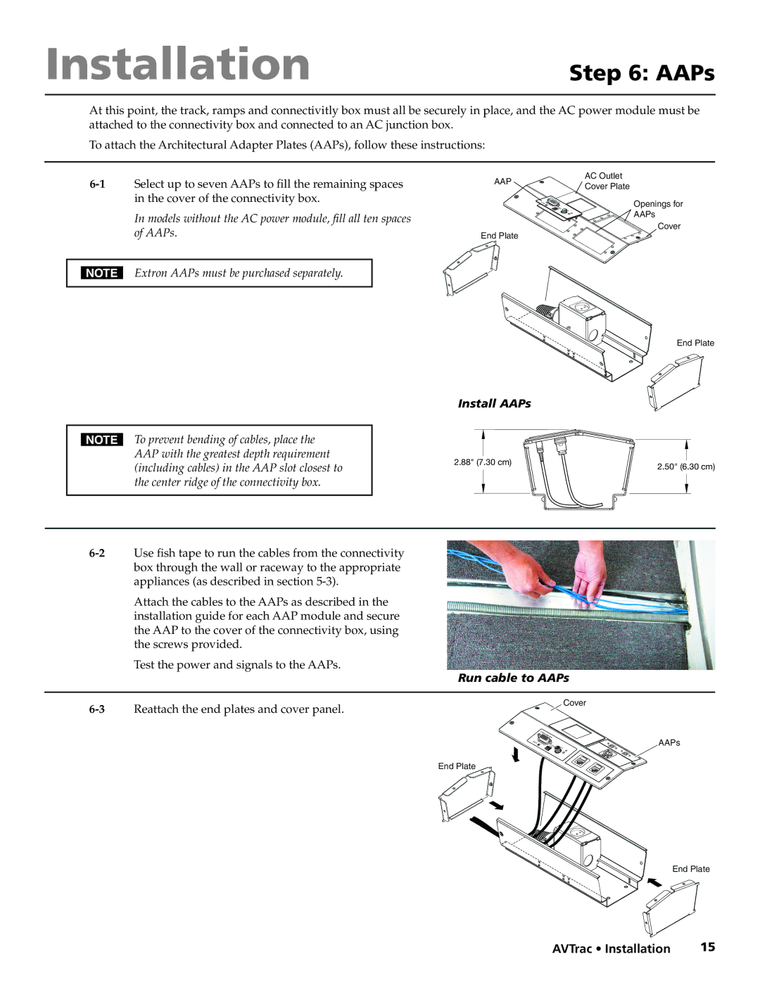
At this point, the track, ramps and connectivitly box must all be securely in place, and the AC power module must be attached to the connectivity box and connected to an AC junction box.
To attach the Architectural Adapter Plates (AAPs), follow these instructions:
In models without the AC power module, fill all ten spaces of AAPs.
AAP | AC Outlet | |
Cover Plate | ||
| ||
| Openings for | |
| AAPs | |
End Plate | Cover | |
|
NExtron AAPs must be purchased separately.
End Plate
Install AAPs
N To prevent bending of cables, place the |
|
|
|
| |
|
|
|
| ||
AAP with the greatest depth requirement |
|
|
|
| |
2.88" ( | 7. | 30 cm) | |||
(including cables) in the AAP slot closest to | |||||
|
|
|
| ||
|
|
|
| ||
the center ridge of the connectivity box. |
|
|
|
| |
|
|
|
| ||
|
|
|
|
| |
Attach the cables to the AAPs as described in the installation guide for each AAP module and secure the AAP to the cover of the connectivity box, using the screws provided.
Test the power and signals to the AAPs.
Run cable to AAPs
Reattach the end plates and cover panel. |
|
|
|
| Cover | |
|
|
|
|
| ||
|
| P |
|
|
|
|
|
| AA SI | 80xi5 |
|
|
|
|
|
| RGB |
| ||
|
|
|
|
| ||
| O | R |
| T |
|
|
| UDIA | COMPUTE | SELEC |
| ||
|
|
|
|
| SHIFTH | |
|
|
|
| INPUT | ||
End Plate
2.50" (6.30 cm)
AAPs
End Plate
AVTrac • Installation | 15 |
