68-1034-02 Rev. A specifications
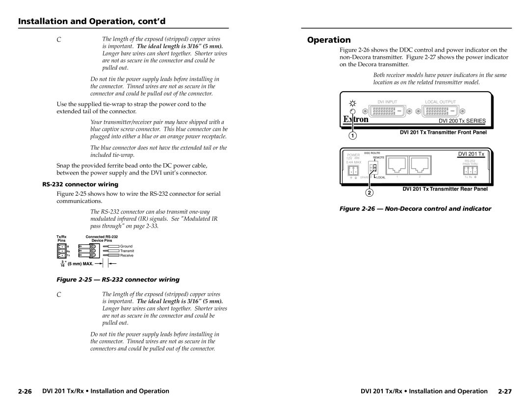
Extron Electronics is a renowned manufacturer of innovative audio-visual solutions, known for providing high-quality products that serve a variety of industries. Among their extensive portfolio, the Extron 68-1034-02 Rev. A stands out as a sophisticated educational tool designed to enhance the presentation experience in classrooms and lecture halls.The Extron 68-1034-02 Rev. A is primarily an instructional tool enabling educators to manage and distribute audio and video signals efficiently. One of its main features is its ability to support multiple input sources, including HDMI, VGA, and audio inputs, allowing for seamless integration of various devices. This flexibility ensures that educators can utilize the technology they are most comfortable with, whether it be laptops, tablets, or desktop computers.
This device employs advanced scaling technology, which ensures that all content is displayed at an optimal resolution regardless of the source. This is critical in educational environments where clarity and detail can significantly impact learning. By utilizing high-performance scaling algorithms, the 68-1034-02 Rev. A guarantees that images maintain their quality during transitions, providing a consistent viewing experience.
One of the standout characteristics of the Extron 68-1034-02 Rev. A is its user-friendly interface. The device features a straightforward control layout with clearly labeled buttons for ease of operation. This is particularly essential in educational settings where instructors may not be tech-savvy. Additionally, the device can be configured for remote management, allowing IT personnel to troubleshoot and manage settings from a distance, thereby enhancing operational efficiency.
Another significant technology embedded in this model is its robust signal processing capabilities. The device boasts low latency, ensuring that audio and video synchronization is maintained even during demanding presentations. This is crucial in maintaining audience engagement, as any delay can disrupt the flow of information.
Moreover, the Extron 68-1034-02 Rev. A includes comprehensive audio control features, allowing educators to adjust sound levels and equalization in real-time. This ensures that every participant in the room can hear the presentation clearly, which is vital for effective communication.
In summary, the Extron 68-1034-02 Rev. A is an exemplary product specifically tailored for educational environments. With its multiple input capabilities, advanced scaling technology, user-friendly design, low-latency processing, and audio control features, it stands as a testament to Extron's commitment to enhancing the learning experience through innovative audiovisual solutions.

