Installation and Operation, cont’d

Terminating shielded cable

NThe transmitter and receiver pair works with unshielded twisted pair (UTP) or shielded twisted pair (STP) cables; but, to ensure FCC Class A and CE compliance, STP cables are recommended.

The Tx/Rx includes four shielded RJ-45 connectors and a length of self-adhesive shielded tape that you can use to make the STP cables that connect the transmitter and receiver.

NExtron supplies the connectors and the shielded tape. You must supply the CAT 5, 5e, or 6 STP cable.

Terminate the STP cable as follows:

1.

Peel back the cable shielding (figure 2-21) from the


end of the cable the length of the RJ-45 connector body


(approximately 7/8" [2.2 cm]) and fold it back.

Peel back shield and fold back.

Figure 2-21 — Peeling back the cable shielding

2.

Cut away and discard the clear cellophane inner wrapper


from the end of the cable back to the folded-over cable


shielding.

3.

Peel the backing off the self-adhesive shielded aluminum


tape and wrap it around the folded-over cable shielding,


slightly overlapping the beginning of the tape


(figure 2-22).

Aluminum Tape

Wrap tape around folded foil shielding.

Slightly overlap.


Cut and save the excess tape


for other connectors.

Figure 2-22 — Wrapping the shielded tape

4.

Cut the unused portion of the shielded tape and retain for


shielding other RJ-45 connectors.

5.

Crimp the RJ-45 cable in the normal manner, folding the


tangs at the end of the connector over the shielded tape


(figure 2-23).

Crimped Connector

Figure 2-23 — Crimped RJ-45 connector

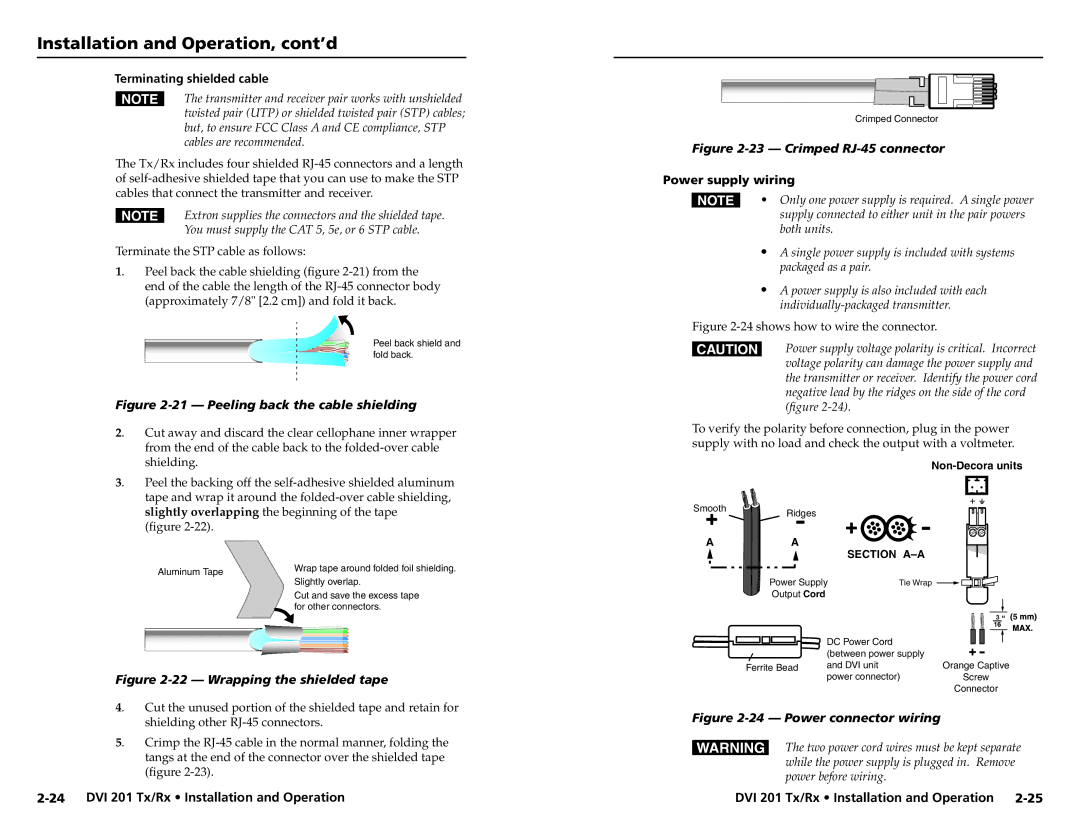
Power supply wiring

N• Only one power supply is required. A single power supply connected to either unit in the pair powers both units.

A single power supply is included with systems packaged as a pair.

A power supply is also included with each individually-packaged transmitter.

Figure 2-24 shows how to wire the connector.

CPower supply voltage polarity is critical. Incorrect voltage polarity can damage the power supply and the transmitter or receiver. Identify the power cord negative lead by the ridges on the side of the cord (figure 2-24).

To verify the polarity before connection, plug in the power supply with no load and check the output with a voltmeter.

Non-Decora units

Smooth Ridges

A

A


SECTION A–A


Power Supply

Tie Wrap


Output Cord


3 5


DC Power Cord


(between power supply


Ferrite Bead

and DVI unit

Orange Captive


power connector)

Screw


Connector

Figure 2-24 — Power connector wiring

WThe two power cord wires must be kept separate while the power supply is plugged in. Remove

power before wiring.

2-24 DVI 201 Tx/Rx • Installation and Operation

DVI 201 Tx/Rx • Installation and Operation 2-25

Page 20
Image 20
Extron electronic 68-1034-02 Rev. A user manual Terminating shielded cable, Power supply wiring

68-1034-02 Rev. A specifications

Extron Electronics is a renowned manufacturer of innovative audio-visual solutions, known for providing high-quality products that serve a variety of industries. Among their extensive portfolio, the Extron 68-1034-02 Rev. A stands out as a sophisticated educational tool designed to enhance the presentation experience in classrooms and lecture halls.

The Extron 68-1034-02 Rev. A is primarily an instructional tool enabling educators to manage and distribute audio and video signals efficiently. One of its main features is its ability to support multiple input sources, including HDMI, VGA, and audio inputs, allowing for seamless integration of various devices. This flexibility ensures that educators can utilize the technology they are most comfortable with, whether it be laptops, tablets, or desktop computers.

This device employs advanced scaling technology, which ensures that all content is displayed at an optimal resolution regardless of the source. This is critical in educational environments where clarity and detail can significantly impact learning. By utilizing high-performance scaling algorithms, the 68-1034-02 Rev. A guarantees that images maintain their quality during transitions, providing a consistent viewing experience.

One of the standout characteristics of the Extron 68-1034-02 Rev. A is its user-friendly interface. The device features a straightforward control layout with clearly labeled buttons for ease of operation. This is particularly essential in educational settings where instructors may not be tech-savvy. Additionally, the device can be configured for remote management, allowing IT personnel to troubleshoot and manage settings from a distance, thereby enhancing operational efficiency.

Another significant technology embedded in this model is its robust signal processing capabilities. The device boasts low latency, ensuring that audio and video synchronization is maintained even during demanding presentations. This is crucial in maintaining audience engagement, as any delay can disrupt the flow of information.

Moreover, the Extron 68-1034-02 Rev. A includes comprehensive audio control features, allowing educators to adjust sound levels and equalization in real-time. This ensures that every participant in the room can hear the presentation clearly, which is vital for effective communication.

In summary, the Extron 68-1034-02 Rev. A is an exemplary product specifically tailored for educational environments. With its multiple input capabilities, advanced scaling technology, user-friendly design, low-latency processing, and audio control features, it stands as a testament to Extron's commitment to enhancing the learning experience through innovative audiovisual solutions.