Model 8/10 PLUS Operation and Configuration
Rear Panel
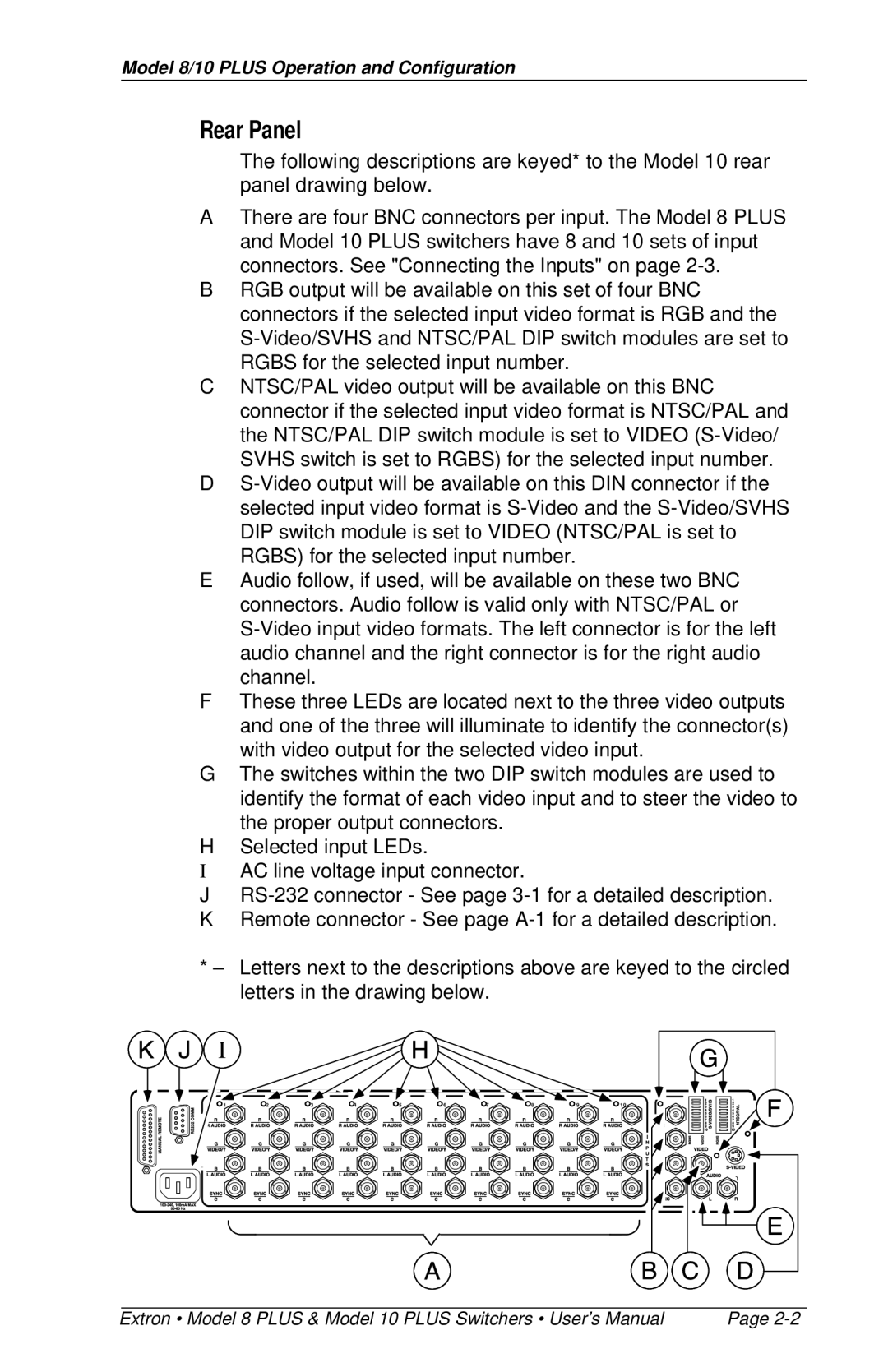
The following descriptions are keyed* to the Model 10 rear panel drawing below.
AThere are four BNC connectors per input. The Model 8 PLUS and Model 10 PLUS switchers have 8 and 10 sets of input connectors. See "Connecting the Inputs" on page
BRGB output will be available on this set of four BNC connectors if the selected input video format is RGB and the
CNTSC/PAL video output will be available on this BNC connector if the selected input video format is NTSC/PAL and the NTSC/PAL DIP switch module is set to VIDEO
D
EAudio follow, if used, will be available on these two BNC connectors. Audio follow is valid only with NTSC/PAL or
FThese three LEDs are located next to the three video outputs and one of the three will illuminate to identify the connector(s) with video output for the selected video input.
GThe switches within the two DIP switch modules are used to identify the format of each video input and to steer the video to the proper output connectors.
HSelected input LEDs.
IAC line voltage input connector.
J
KRemote connector - See page
*– Letters next to the descriptions above are keyed to the circled letters in the drawing below.
1 | 2 | 3 | 4 | 5 | 6 | 7 | 8 | 9 | 1 0 |
Extron • Model 8 PLUS & Model 10 PLUS Switchers • User’s Manual | Page |
