Model 8/10 PLUS Operation and Configuration
Output Select DIP Switch Setting
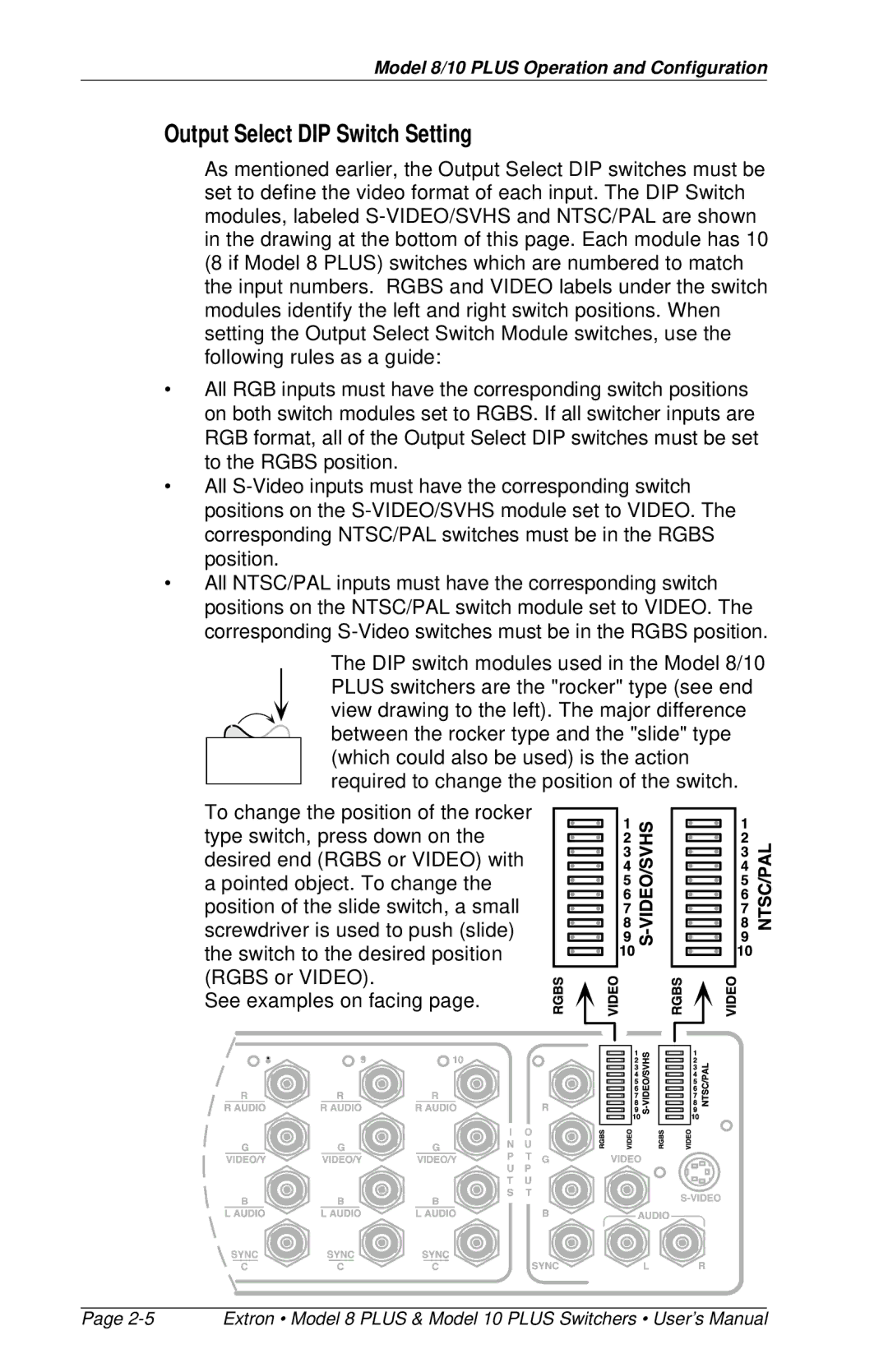
As mentioned earlier, the Output Select DIP switches must be set to define the video format of each input. The DIP Switch modules, labeled
•All RGB inputs must have the corresponding switch positions on both switch modules set to RGBS. If all switcher inputs are RGB format, all of the Output Select DIP switches must be set to the RGBS position.
•All
•All NTSC/PAL inputs must have the corresponding switch positions on the NTSC/PAL switch module set to VIDEO. The corresponding
The DIP switch modules used in the Model 8/10 PLUS switchers are the "rocker" type (see end view drawing to the left). The major difference between the rocker type and the "slide" type (which could also be used) is the action required to change the position of the switch.
To change the position of the rocker type switch, press down on the desired end (RGBS or VIDEO) with a pointed object. To change the position of the slide switch, a small screwdriver is used to push (slide) the switch to the desired position (RGBS or VIDEO).
See examples on facing page.
Page | Extron • Model 8 PLUS & Model 10 PLUS Switchers • User’s Manual |