Model 8/10 PLUS Operation and Configuration
Model 8/10 Switcher Operation
The Model 8/10 PLUS switchers enable the output to be switched from anyone of 8 or 10 inputs (A)* and the following formats are supported:
•RGBS – RGB with separate composite sync
•RGsB – RGB with sync on green
•Monochrome Composite Video
•NTSC/PAL (Composite) Video w/Stereo Audio follow
•
When an input is selected, an LED will illuminate green next to the selected BNC input connectors on the rear panel (H)*.
Three sets of output connectors are used for the four different video format outputs. They are:
•RGB (RGBS or RGsB) – 4 BNC connectors (B)*
•VIDEO (NTSC/PAL) – 1 BNC connector (C)*
•
Audio, if used, is available on the two output BNC connectors labeled AUDIO (L and R) (E)*.
Only one set of output connectors is active at a time. The current active set is identified by an illuminated LED next to the active output connector(s) (F)*.
The Output Select DIP Switch (G)* settings will determine which of the three output connectors that the selected input will be directed to. These switches must be set for each input to match the incoming format. There are two switch modules, the left switch module is for
Front Panel
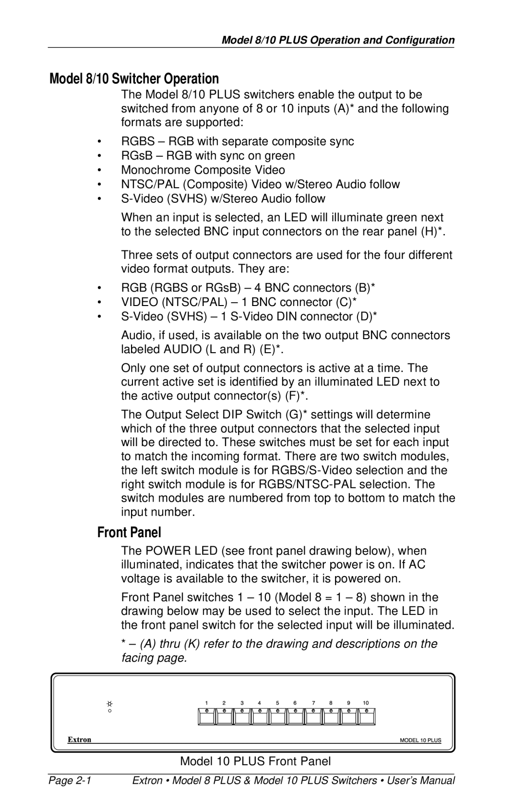
The POWER LED (see front panel drawing below), when illuminated, indicates that the switcher power is on. If AC voltage is available to the switcher, it is powered on.
Front Panel switches 1 – 10 (Model 8 = 1 – 8) shown in the drawing below may be used to select the input. The LED in the front panel switch for the selected input will be illuminated.
*– (A) thru (K) refer to the drawing and descriptions on the facing page.
Model 10 PLUS Front Panel
Page | Extron • Model 8 PLUS & Model 10 PLUS Switchers • User’s Manual |