DVC501SD specifications
The Extron Electronic DVC501SD is a sophisticated device designed for video scaling and conversion, catering to various audiovisual applications. This versatile tool is particularly valuable for professional environments where high-quality video output is essential. The DVC501SD stands out through its array of features, advanced technologies, and user-friendly characteristics, making it an excellent choice for broadcasting, videoconferencing, and other multimedia usage.One of the main features of the DVC501SD is its ability to convert and scale video signals from multiple sources. It supports a wide range of resolutions, ensuring compatibility with various video formats. The device features a built-in upscaler that can handle 4:3 and 16:9 aspect ratios, allowing users to optimize video quality based on their display needs. This capability is crucial for presentations or events where clarity and detail are paramount.
The DVC501SD utilizes Extron’s proprietary video processing technologies, ensuring that color accuracy and video integrity are maintained throughout the signal conversion process. This technology includes advanced filtering and dynamic range control, which enhances overall video performance. The device can deliver high-quality outputs with low latency, making it ideal for live streaming and real-time video applications.
Another notable characteristic is its straightforward user interface. The DVC501SD features an intuitive front panel with easily accessible buttons for quick adjustments. Additionally, it includes an LCD display that provides essential information about input sources and output resolutions, ensuring users can manage settings conveniently.
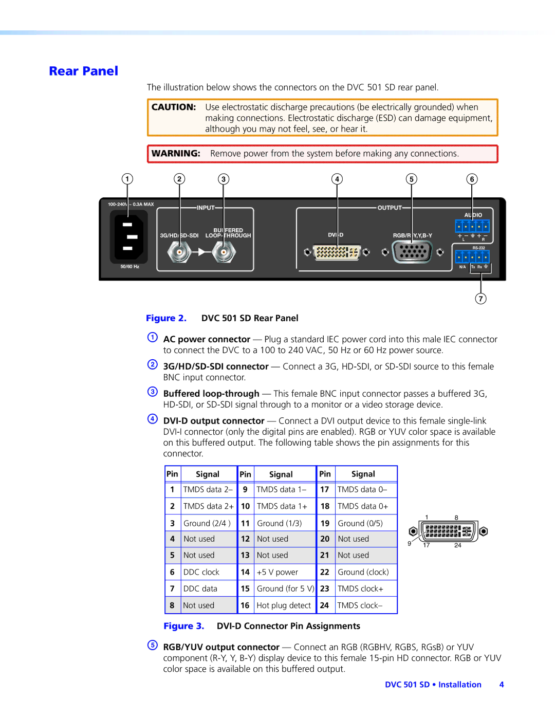
The DVC501SD is also equipped with various input and output options, including HDMI, Composite, and S-Video, providing flexibility in connecting different devices. The robust build quality ensures that it can withstand the rigors of professional use, making it a reliable choice for any AV setup.
The device supports both analog and digital audio, allowing for a seamless integration of sound with video. This is especially important in environments where audio-visual synchronization enhances the overall experience.
With its blend of functionality, ease of use, and adaptability, the Extron Electronic DVC501SD stands out as a top choice in the realm of video scaling and conversion. Whether for corporate presentations, educational settings, or live events, it delivers exceptional performance, making it a valuable asset for any professional AV solution.

