Installation, cont’d
PRELIMINARY
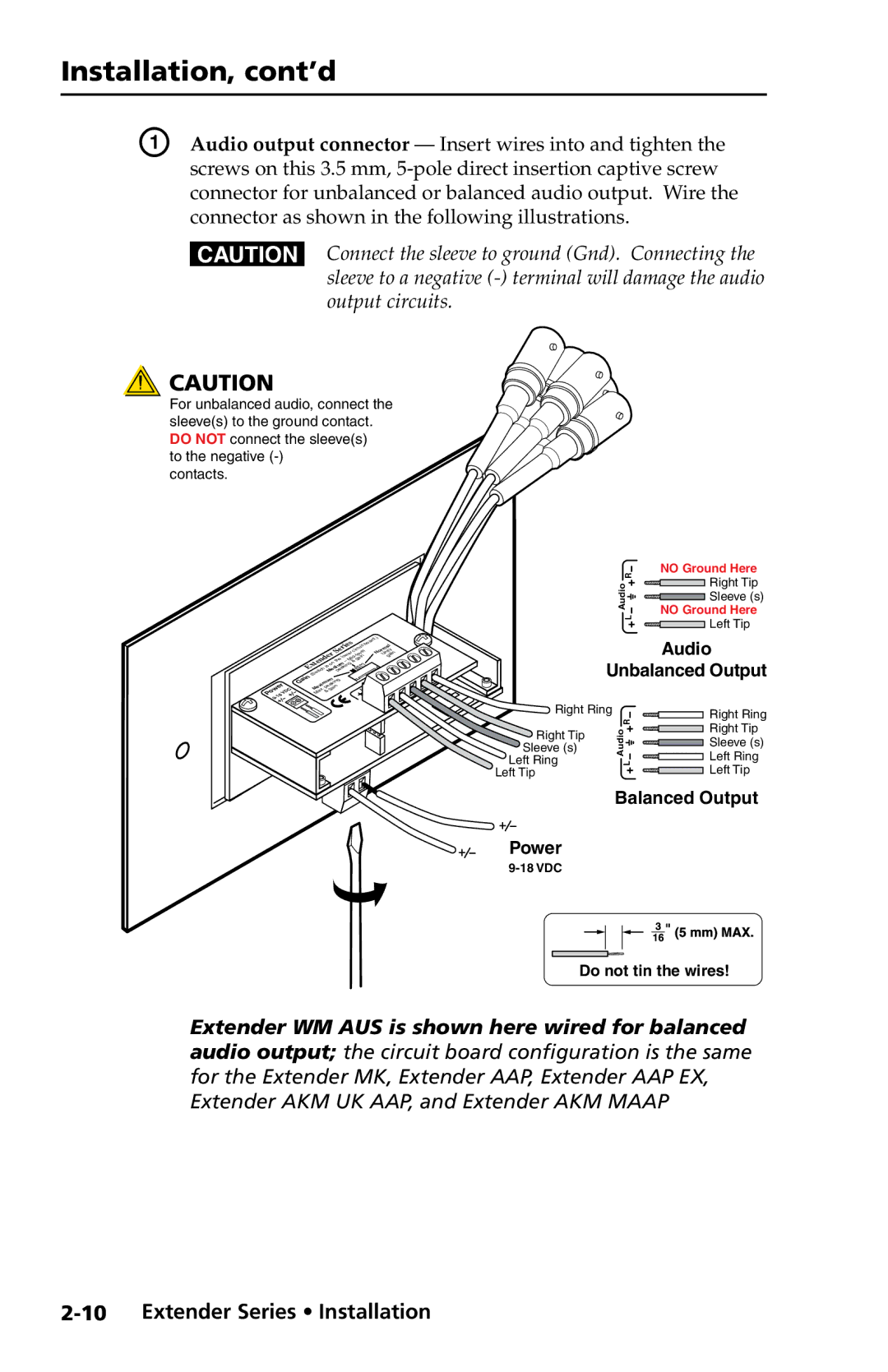
A | Audio output connector — Insert wires into and tighten the |
| screws on this 3.5 mm, |
| connector for unbalanced or balanced audio output. Wire the |
| connector as shown in the following illustrations. |
| C Connect the sleeve to ground (Gnd). Connecting the |
| sleeve to a negative |
| output circuits. |
![]() CAUTION
CAUTION
For unbalanced audio, connect the sleeve(s) to the ground contact. DO NOT connect the sleeve(s)
to the negative (-) contacts.
|
|
|
|
|
|
|
|
|
|
|
|
| .) | |
|
|
|
|
|
|
|
|
|
|
|
|
| d | |
|
|
|
|
|
|
|
| rie | oar | rm y | ||||
|
|
|
|
|
|
|
|
|
| s | itb |
| l | |
|
|
|
|
|
|
|
|
|
|
|
| u |
| a |
|
|
|
|
|
|
|
| e rcircel |
| o it | ||||
|
|
|
|
|
|
| S |
| e | v |
| N n in | ||
|
|
|
|
| r |
|
| w |
| U a | ||||
|
|
|
|
| e |
|
| lo | id ain |
| g | |||
|
|
|
| d |
|
| e | M | g |
|
| |||
|
|
|
| n |
| th |
|
|
|
| ||||
|
|
| te |
| n |
|
|
| ||||||
|
| x |
|
| o iumkin |
|
|
|
| |||||
|
|
|
|
| is | d a |
|
|
|
| ||||
|
|
|
| h | e e |
|
|
|
|
| ||||
|
| E witc M p |
|
|
|
|
|
| ||||||
|
| Gain | (S | im a |
|
|
|
|
|
|
| |||
|
|
|
|
| m g |
|
|
|
|
|
| |||
werD |
|
| ukin |
|
|
|
|
|
| |||||
| a & |
|
|
|
|
|
|
|
| |||||
|
|
|
| x e |
|
|
|
|
|
|
|
| ||
|
| C | a | .p ain |
|
|
|
|
|
| ||||
| M |
|
|
|
|
|
|
|
|
|
| |||
9 | 8V |
|
|
|
|
|
|
|
|
|
|
| ||
NO Ground Here
R | Right Tip | |
Audio | ||
Sleeve (s) | ||
L | NO Ground Here | |
Left Tip | ||
|
|
|
| Audio |
| Unbalanced Output | ||
Right Ring |
| Right Ring | |
|
| R | |
|
| Right Tip | |
Right Tip |
| Audio | |
| Sleeve (s) | ||
Sleeve (s) |
| ||
Left Ring |
| L | Left Ring |
Left Tip |
|
| Left Tip |
Balanced Output
Power
Do not tin the wires!
Extender WM AUS is shown here wired for balanced audio output; the circuit board configuration is the same for the Extender MK, Extender AAP, Extender AAP EX, Extender AKM UK AAP, and Extender AKM MAAP