HDMI 201 Tx/Rx specifications
Extron Electronics has consistently been at the forefront of providing high-quality professional AV solutions, and their HDMI 201 Tx/Rx model stands as a testament to this legacy. Designed for superior performance in distributing HDMI signals, the HDMI 201 Tx/Rx offers a reliable solution for any professional installation environment, such as classrooms, conference rooms, and commercial spaces.One of the standout features of the HDMI 201 Tx/Rx is its ability to extend HDMI signals beyond typical limitations. With support for high-definition video up to 1080p and audio formats, it ensures that users experience pristine image quality without degradation. This model can extend signals up to 200 feet (60 meters) over a standard category cable, allowing for flexible installations without compromising quality.
The HDMI 201 Tx/Rx utilizes advanced technologies including Extron's unique engineering that incorporates built-in EDID management. This feature simplifies configuration by allowing the transmission of data between display devices and source components, ensuring compatibility and optimal performance. Additionally, the device supports a wide range of video resolutions and audio formats, making it adaptable for various applications and user needs.
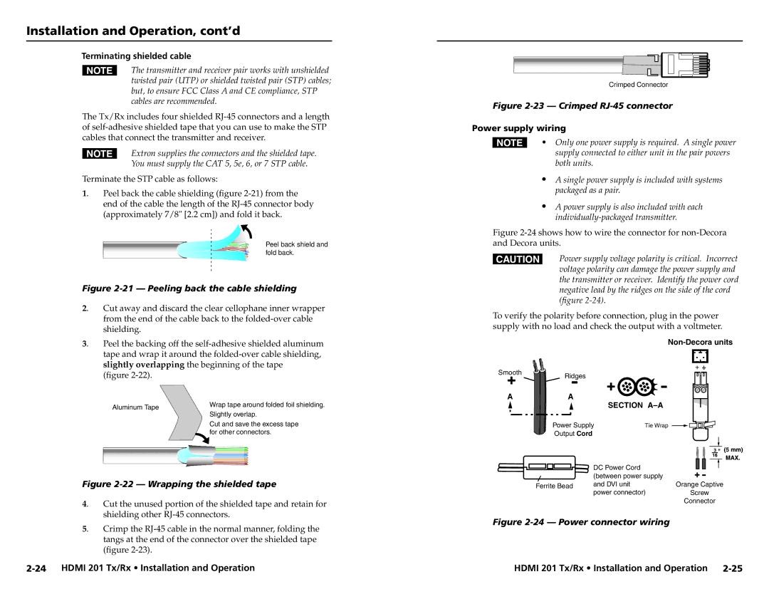
Another remarkable characteristic is the HDMI 201's compact and robust design. The unit is housed in a sturdy enclosure, making it suitable for rack mounting or placement in tight spaces without sacrificing performance. Furthermore, the Transmitter and Receiver are powered via a single power supply, facilitating easier installation and reducing clutter.
The Extron HDMI 201 Tx/Rx also features a user-friendly interface, with LED indicators that provide clear status information at a glance. This allows AV managers and technicians to quickly troubleshoot connection issues and monitor the system's performance, enhancing reliability and ease of use.
In conclusion, the Extron HDMI 201 Tx/Rx is a powerful solution for the transmission and extension of HDMI signals in professional settings. With its exceptional video and audio support, advanced features like EDID management, compact design, and user-centric interface, it represents a commitment to quality and innovation in the realm of audio-visual technology. This makes the HDMI 201 Tx/Rx an ideal choice for any AV professional seeking to enhance their installations and deliver superb content quality.

