MLS 304MA, MLS 304SA, MLS 406, MLS 406MA, MLS 406SA
MediaLink Switchers
Safety Instructions English
Precautions
Consignes de Sécurité Français
Sicherheitsanleitungen Deutsch
Quick Start MLS 304MA, MLS 406, MLS 406MA
Installation
Video Configuration
Table of Contents
Table of Contents, cont’d
One
Introduction
Features
About this Manual
About the MLS 304 Series and the MLS 406 Series
Two
UL/Safety Requirements
Installation
Important Safety Instructions
MLS 304 Series, MLS 406 Series Installation
Tabletop use
Mounting the Switcher
Rack mounting
Power connection
Power, input, and control connections
�MLS 304 Series, MLS 406 Series Installation
Rear Panels and Cabling
Balanced Mono Input
Input Type Signal BNC Color
� MLS 304 Series, MLS 406 Series Installation
Installation, cont’d
Control connection
IR Link IR signal repeater
That has an external power supply
Video outputs
Video output, local monitor, and audio output connections
Audio outputs
Unbalanced Mono Output Balanced Mono Output
Ohm Total Load
Wiring for 4 ohm or 8 ohm speakers MA models
Speakers Tapped at 7.5 Watts Each Equals 15 Watts Total
Stereo Output
Wiring for 4 ohm or 8 ohm speakers SA models
Examples of speaker layouts
Speaker arrangement examples
MLC
Application Diagrams
Extron
Projector
MLC
Three
Front Panel Features and Operation
Operation and Setup
� MLS 304 Series, MLS 406 Series Operation and Setup
Minimum threshold at least 21%
Front panel security lockout executive modes
MLS 304 Series, MLS 406 Series Operation and Setup
Resetting the switcher
Setting Up and Optimizing the Audio
�MLS 304 Series, MLS 406 Series Operation and Setup
Adjusting audio input levels
Configuring Lineout and Preamp output levels
Signal detection threshold
Making adjustments
Clipping level
Normal range
Standard mode mode
Video Signal Routing
DA distribution amplifier mode mode
RGB follow mode mode
Mode Selected input Input special conditions Monitor Output
Remote Control
Mode
If the switcher does not respond to controls
Troubleshooting
If the image does not appear or there is no sound
Preliminary
Four
RS-232 Programmer’s Guide
Serial Communication
Host-to-MLS communications
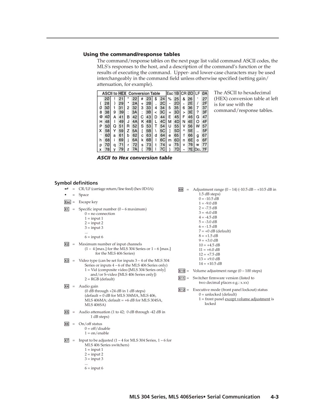
Symbol definitions
Using the command/response tables
MLS 304 Series, MLS 406Series Serial Communication
Command Ascii Command Response Additional description
Command/response table for SIS commands
Aux/Mix input
Audio status for the active input
Firmware version, part number & information requests
Command Ascii Command Response ? values
Command/response table for special function SIS commands
Using the control program
Installing the software
Control Software for Windows
Special features
User Mode Screen
Switcher MLS Config Screen
Preliminary
File menu options
Saving and restoring configurations
Updating firmware
Follow the on-screen instructions
Key to file names
Using the help program
File name Description
AAppendix a
Reference Material
Specifications
Video
Video input and loop-through
Audio
Sync
MLS 304 Series, MLS 406 Series Reference Material A-�
Audio input
Audio output mono power amp MLS 304MA, MLS 406MA only
Audio output Lineout and Preamp
Included parts
Control/remote switcher
Audio output stereo power amp MLS 304SA, MLS 406SA only
General
Optional accessories
Part Numbers and Accessories
Included parts Replacement Part number
Accessory Part number
Audio Reference Levels
Frequency Response Graph for the Loudness Feature
MLS 304MA audio block diagram
Audio Block Diagrams
Utinpse LE CT
MLS 304SA audio block diagram
Inputs
MLS 406, MLS 406MA audio block diagram
MLS 304 Series, MLS 406 Series Reference Material A-11
MLS 406SA audio block diagram
This page was deliberately left blank
FCC Class a Notice Extron’s Warranty
Extron Electronics, USA