Installing RGB 320 Switching Interface Components • Chapter 2
Connecting the RGB 320 Switching Interface
The RGB 320 has six inputs and two outputs, plus connections for
Each RGB 320 input has five BNC connectors to allow for RGsB, RGBS or RGBHV input. There are also connectors for stereo audio. Although different devices can be used as inputs to the RGB 320, it was designed to be the center of a switching interface system, using buffer devices mounted in a wall, a table or a podium. Extron makes three types of buffer units that provide remote input to the RGB 320. In addition, the RGB 320 is a switcher, allowing one of six inputs to be displayed through a projector or monitor.
The two buffered outputs are identical, with six BNC connectors and
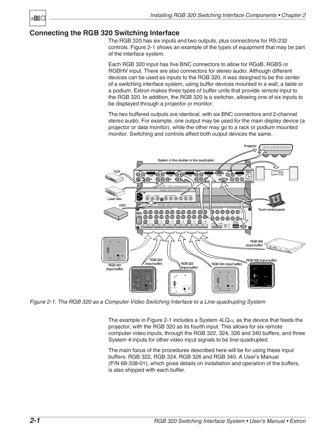
Figure 2-1. The RGB 320 as a Computer Video Switching Interface to a Line-quadrupling System
The example in Figure
The main focus of the procedures described here will be for using these input buffers: RGB 322, RGB 324, RGB 326 and RGB 340. A User’s Manual
(P/N
RGB 320 Switching Interface System • User’s Manual • Extron |