Installing RGB 320 Switching Interface Components • Chapter 2
Buffer Input Cables
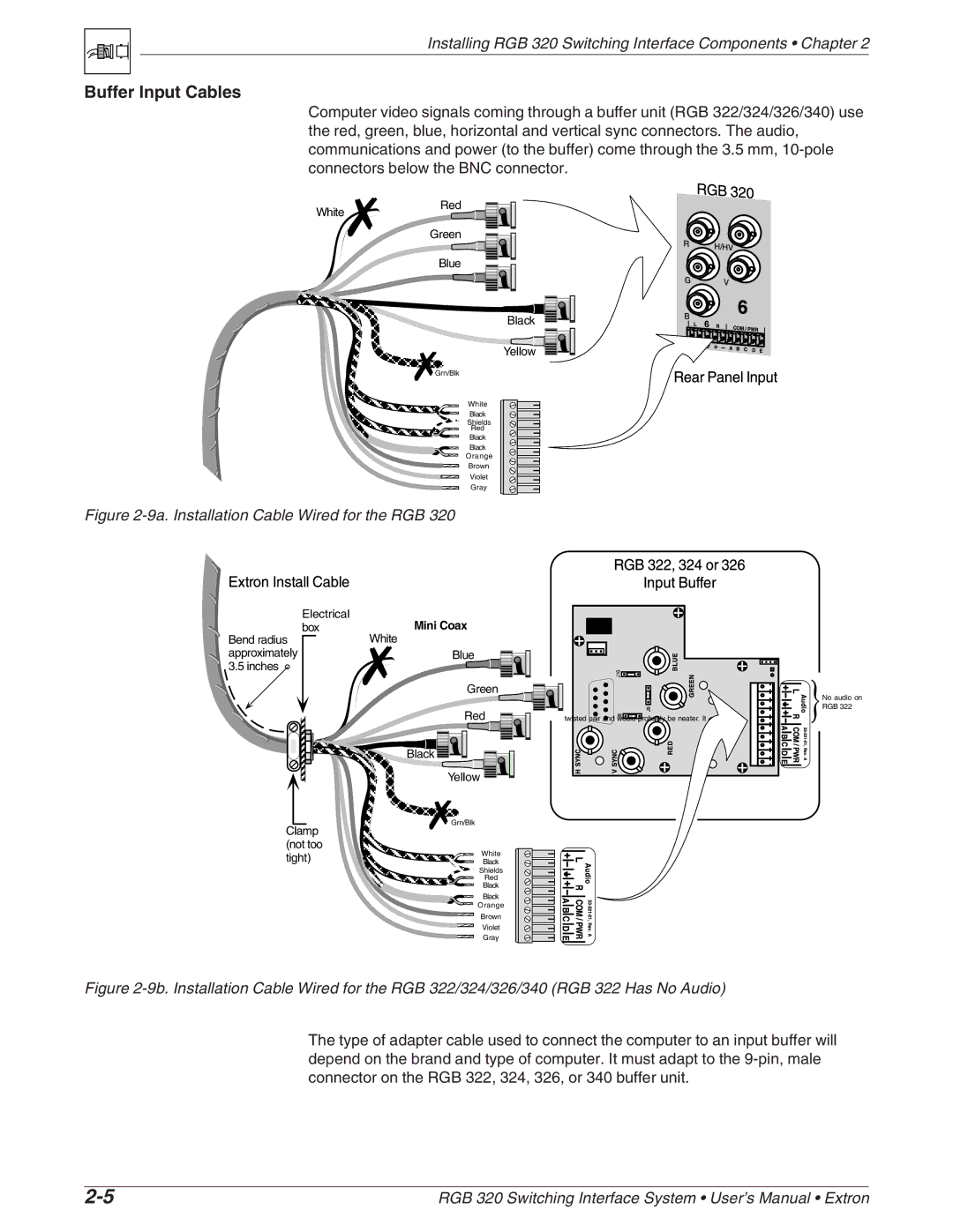
Computer video signals coming through a buffer unit (RGB 322/324/326/340) use the red, green, blue, horizontal and vertical sync connectors. The audio, communications and power (to the buffer) come through the 3.5 mm,
White
Red
Green
Blue
Black
Yellow
Grn/Blk
White
Black
Shields
Red
Black
Black
Orange
Brown
Violet
Gray
Figure 2-9a. Installation Cable Wired for the RGB 320
Electrical | Mini Coax |
box |
Bend radius | White |
|
approximately | Blue |
|
3.5 inches |
|
|
| Green |
|
| Red | twisted pair and would probably be neater. It |
| Black |
|
| Yellow |
|
Clamp | Grn/Blk | |
| ||
(not too | White | |
tight) | ||
Black |
Shields
Red
Black
Black
Orange
Brown
Violet
Gray
No audio on RGB 322
Figure 2-9b. Installation Cable Wired for the RGB 322/324/326/340 (RGB 322 Has No Audio)
The type of adapter cable used to connect the computer to an input buffer will depend on the brand and type of computer. It must adapt to the
RGB 320 Switching Interface System • User’s Manual • Extron |
