| Installing RGB 320 Switching Interface Components • Chapter 2 | |
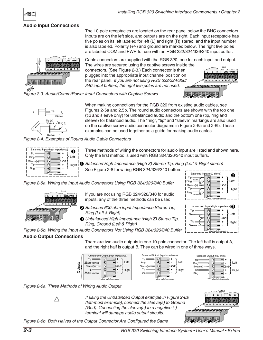
Audio Input Connections |
|
|
| The | |
| Inputs are on the left side, and outputs are on the right. Each input receptacle has | |
| five poles on its left labeled for left (L) and right (R) stereo, and the input number | |
| is also labeled. Polarity | |
| are labeled COM and PWR for use with an RGB 322/324/326/340 input buffer. | |
Input | Cable connectors are supplied with the RGB 320, one for each input and output. | |
L 2 R | ||
| The wires are secured using the captive screws inside the | Input |
| connectors. (See Figure | |
| L 2 R | |
| plugged into the appropriate input channel position on |
|
| the rear panel. If you are not using RGB 322/324/326/ |
|
| 340 input buffers, the right five poles are not used. |
|
Figure |
| |
![]()
![]() Tip
Tip
Sleeve
Tip (+)
![]() Ring
Ring
![]() Sleeve
Sleeve ![]()
When making connections for the RGB 320 from existing audio cables, see Figures
Figure 2-4. Examples of Round Audio Cable Connectors
Balanced Input (high impedance) | Three methods of wiring the connectors for audio input are listed and shown here. | ||||
|
|
| |||
Tip |
| Only the first method is used with RGB 324/326/340 input buffers. |
| ||
Ring | Left |
| |||
Sleeve(s) | Gnd | Balanced High Impedance (High Z) Stereo Tip, Ring (Left & Right stereo) | |||
Tip | Right | ||||
|
|
|
| ||
Ring |
| See Figure |
|
| |
|
|
|
| ||
| other half of connector |
| Balanced Input (600 ohms) | ||
|
|
| Tip |
| |
Figure | Ring 600 ohm | Left | |||
Sleeve(s) | Gnd | ||||
|
|
| |||
|
|
| Tip | Right | |
|
|
| Input | If you are not using RGB 324/326/340 for audio | Ring |
L | 2 | R |
| ||
| 600 ohm | ||||
|
|
|
| inputs, any of the three methods can be used. | other half of connector |
![]() Balanced 600 ohm input Impedance Stereo Tip,
Balanced 600 ohm input Impedance Stereo Tip,
Ring (Left & Right)
![]() Unbalanced High Impedance (High Z) Stereo Tip, Ring, Ground (Left & Right)
Unbalanced High Impedance (High Z) Stereo Tip, Ring, Ground (Left & Right)
Figure 2-5b. Wiring the Input Audio Connectors Not Using RGB 324/326/340 Buffer
Unbalanced Input (high impedance)![]()
Tip |
|
Sleeve | Left |
| Gnd |
Tip | Right |
Sleeve |
|
| other half of connector |
Audio Output Connections
There are two audio outputs in one
Outputs![]()
![]()
Unbalanced Output (high impedance)
Tip | Left |
See warning. | |
Sleeve(s) | Gnd |
Tip | Right |
See warning. |
|
| other half of connector |
Balanced Output (high impedance) |
| Balanced Output (600 ohms) | ||
Tip |
| Left | Tip | Left |
Ring | Gnd | Ring | ||
Sleeve(s) |
| Sleeve(s) | Gnd | |
Tip |
| Right | Tip | Right |
Ring |
|
| Ring |
|
| other half of connector |
|
| other half of connector |
Figure 2-6a. Three Methods of Wiring Audio Output
_________ If using the Unbalanced Output example in Figure 2-6a
(left-most example), connect the sleeve(s) to Ground (Gnd). Connecting the sleeve(s) to a negative (-) terminal will damage audio output circuits.
Figure 2-6b. Both Halves of the Output Connector Are Configured the Same
Output
L | A | R | L | B | R |
RGB 320 Switching Interface System • User’s Manual • Extron |