Chapter 3 • Operating the RGB 320 Panels
Making Input Adjustments from the RGB 320 Front Panel
When adjustments are being made from the front panel, an input buffer or an
![]() ________ Do not make adjustments immediately after switching inputs. Wait for the Horz
________ Do not make adjustments immediately after switching inputs. Wait for the Horz
and Vert frequency values on the LCD panel to stabilize, or for the image on the output display to stabilize. If adjustments are made before that time, they may not be stored.
Turn any of the four adjustment knobs to adjust the current setting for that function, for the selected input – if it is not currently being adjusted from another source. This appears on the LCD screen as the adjustment is being made. When the adjustment is complete, release the knob and, after a 7.5 second
Figure 3-7. Example of the Input Frequencies Being Displayed on the Default Screen
 ________ The LCD display will also show an adjustment that is being made from a remote
buffer unit or an RS-232 device.
However, the buffer unit has priority over the panel and the RS-232 device. (For example, if an RGB 324
has V. Shift selected, turning a knob on the
panel does nothing until after the time-
out.
Figure 3-8. Turn the Appropriate Knob to Adjust an Input Function; the LCD Displays the Action
Four Video and Audio Adjustments
Adjustments
affect both of the RGB 320 outputs; therefore, for best results, observe the primary display (projector), instead of the secondary display (a monitor in a rack or podium), while making the adjustment.
Following is a description of each of the four adjustments. The LCD screen displays the high and low limits for the adjustments, as well as the current value.
Horizontal shift – Moves the displayed image left and right on the screen. This is also called Horizontal Centering.
Vertical shift – Moves the displayed image up and down on the screen. This is also called Vertical Centering.
Video level – A video level control is provided to compensate for a weak or strong video signal. For example, if the signal from input #1 is weak and the signal from input #3 is strong, each signal can be adjusted and stored to memory. This allows for better balance when switching from one input to another. (Unity gain is the middle of the range, at 128.)
Audio level – Adjusts the audio level for the selected input and saves it to memory.
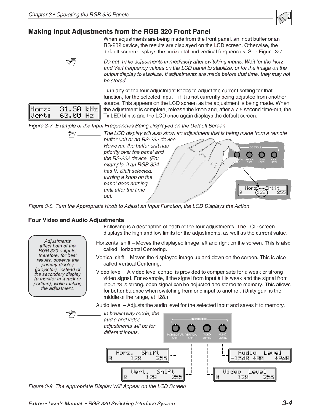
![]() ________ In breakaway mode, the
________ In breakaway mode, the
audio and video adjustments will be for different inputs.
Figure 3-9. The Appropriate Display Will Appear on the LCD Screen
Extron • User’s Manual • RGB 320 Switching Interface System |