Chapter 2 • Installing the RGB 320 Switching Interface Components
Rear Panel Connectors
1
L 1 R
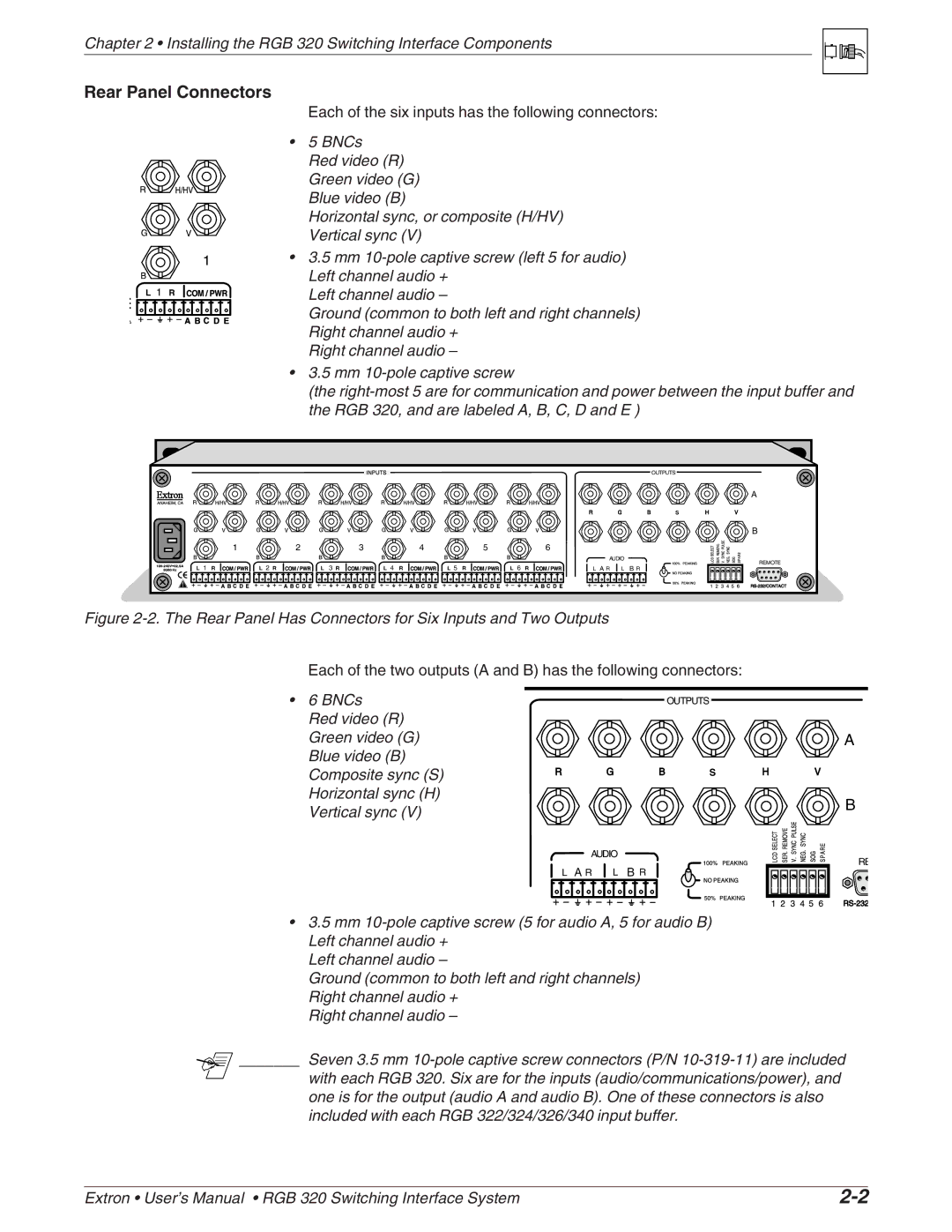
Each of the six inputs has the following connectors:
•5 BNCs
Red video (R) Green video (G) Blue video (B)
Horizontal sync, or composite (H/HV) Vertical sync (V)
•3.5 mm
Left channel audio –
Ground (common to both left and right channels) Right channel audio +
Right channel audio –
•3.5 mm
(the
OUTPUTS
A
S
B
1 | 2 | 3 | 4 | 5 | 6 |
|
|
|
|
|
| AUDIO | REMOTE | |
L 1 R | L 2 R | L 3 R | L 4 R | L 5 R | L 6 R |
|
| |
L A R | L | B R | ||||||
Figure 2-2. The Rear Panel Has Connectors for Six Inputs and Two Outputs
Each of the two outputs (A and B) has the following connectors:
•6 BNCs
Red video (R) Green video (G) Blue video (B) Composite sync (S) Horizontal sync (H) Vertical sync (V)
OUTPUTS
S
![]() AUDIO
AUDIO
L A R L B R
A
B
RE
•3.5 mm
Left channel audio –
Ground (common to both left and right channels) Right channel audio +
Right channel audio –
_______ Seven 3.5 mm
with each RGB 320. Six are for the inputs (audio/communications/power), and one is for the output (audio A and audio B). One of these connectors is also included with each RGB 322/324/326/340 input buffer.
Extron • User’s Manual • RGB 320 Switching Interface System |