Installation and Operation, cont’d
Rear Panel
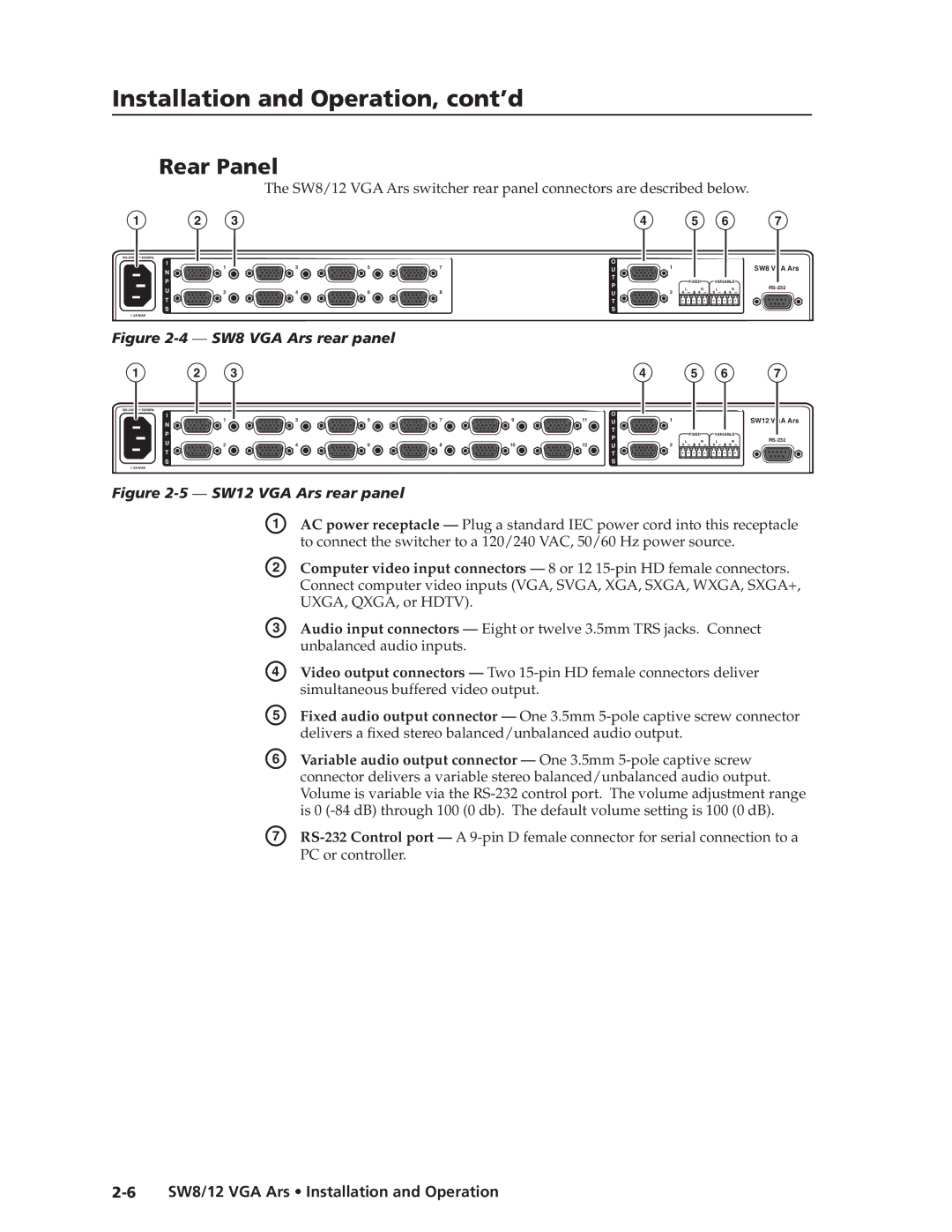
The SW8/12 VGA Ars switcher rear panel connectors are described below.
1 |
| 2 | 3 |
|
|
|
| 4 |
|
| 5 |
| 6 | 7 |
50/60Hz |
|
|
|
|
|
| O |
|
|
|
|
|
| |
| I | 1 | 3 | 5 | 7 |
|
| 1 |
|
|
|
| SW8 VGA Ars | |
| N |
|
| U |
|
|
|
| ||||||
|
|
|
|
|
|
| T |
|
|
|
|
|
| |
| P |
|
|
|
|
|
|
|
| FIXED | VARIABLE |
| ||
|
|
|
|
|
|
| P |
|
| |||||
| U |
|
|
|
|
|
|
| L | R | L | R | ||
| 2 | 4 | 6 | 8 |
|
| U | 2 | ||||||
|
|
|
|
|
|
|
| |||||||
| T |
|
|
|
|
|
|
| ||||||
|
|
|
|
|
|
| T |
|
|
|
|
|
| |
| S |
|
|
|
|
|
| S |
|
|
|
|
|
|
1.2A MAX |
|
|
|
|
|
|
|
|
|
|
|
|
| |
Figure |
|
|
|
|
|
|
|
|
|
| ||||
1 |
| 2 | 3 |
|
|
|
| 4 |
|
| 5 |
| 6 | 7 |
50/60Hz |
|
|
|
|
|
| O |
|
|
|
|
|
| |
| I | 1 | 3 | 5 | 7 | 9 | 11 | 1 |
|
|
|
| SW12 VGA Ars | |
| N | U |
|
|
|
| ||||||||
|
|
|
|
|
|
| T |
|
|
|
|
|
| |
| P |
|
|
|
|
|
|
|
| FIXED | VARIABLE |
| ||
|
|
|
|
|
|
| P |
|
| |||||
| U |
|
|
|
|
|
|
| L | R | L | R | ||
| 2 | 4 | 6 | 8 | 10 | 12 | U | 2 | ||||||
|
|
|
|
|
| |||||||||
| T |
|
|
|
|
| ||||||||
|
|
|
|
|
|
| T |
|
|
|
|
|
| |
| S |
|
|
|
|
|
| S |
|
|
|
|
|
|
1.2A MAX |
|
|
|
|
|
|
|
|
|
|
|
|
| |
Figure 2-5 — SW12 VGA Ars rear panel
A | AC power receptacle — Plug a standard IEC power cord into this receptacle |
| to connect the switcher to a 120/240 VAC, 50/60 Hz power source. |
B | Computer video input connectors — 8 or 12 |
| Connect computer video inputs (VGA, SVGA, XGA, SXGA, WXGA, SXGA+, |
| UXGA, QXGA, or HDTV). |
C | Audio input connectors — Eight or twelve 3.5mm TRS jacks. Connect |
| unbalanced audio inputs. |
D | Video output connectors — Two |
| simultaneous buffered video output. |
E | Fixed audio output connector — One 3.5mm |
| delivers a fixed stereo balanced/unbalanced audio output. |
F | Variable audio output connector — One 3.5mm |
| connector delivers a variable stereo balanced/unbalanced audio output. |
| Volume is variable via the |
| is 0 |
G | |
| PC or controller. |