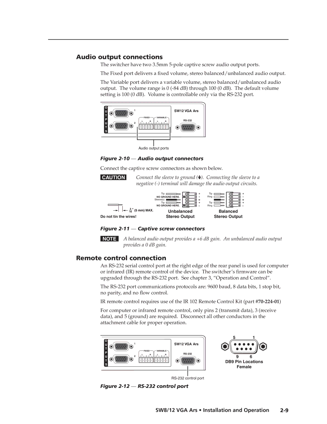
Audio output connections
The switcher have two 3.5mm
The Fixed port delivers a fixed volume, stereo balanced/unbalanced audio output.
The Variable port delivers a variable volume, stereo balanced/unbalanced audio output. The volume range is 0
O | 1 |
|
| SW12 VGA Ars | |
U |
|
| |||
T |
| FIXED | VARIABLE |
| |
P |
|
| |||
| L R | L R | |||
U | 2 | ||||
|
|
|
T
S
Audio output ports
Figure 2-10 — Audio output connectors
Connect the captive screw connectors as shown below.
CConnect the sleeve to ground (![]() ). Connecting the sleeve to a negative
). Connecting the sleeve to a negative
Tip
NO GROUND HERE.
Sleeve(s)
Tip
NO GROUND HERE.
|
|
|
|
|
|
| Unbalanced |
|
|
|
|
|
|
| |
Do not tin the wires! | Stereo Output | ||||||
Tip
Ring
Tip
Ring
Balanced
Stereo Output
Figure 2-11 — Captive screw connectors
NA balanced audio output provides a +6 dB gain. An unbalanced audio output provides a 0 dB gain.
Remote control connection
An
The
IR remote control requires use of the IR 102 Remote Control Kit (part
For computer or infrared remote control, only pins 2 (transmit data), 3 (receive data), and 5 (ground) are required. Disconnect all other conductors in the attachment cable for proper operation.
O |
|
|
|
| 5 | 1 | |
1 |
|
| SW12 VGA Ars |
|
| ||
U |
|
|
|
| |||
T |
| FIXED | VARIABLE |
|
|
| |
P |
|
|
|
| |||
| L R | L R | 9 | 6 | |||
U | 2 | ||||||
|
|
|
T | DB9 Pin Locations | |
S | ||
Female | ||
|
Figure 2-12 — RS-232 control port
SW8/12 VGA Ars • Installation and Operation |