Operationration, cont’d
Front Panel Controls and Indicators
Figure
8
SW6 CV MX
COMPOSITE VIDEO SWITCHER
1 | 2 | 3 | 4 | 5 | 6 | 7 |
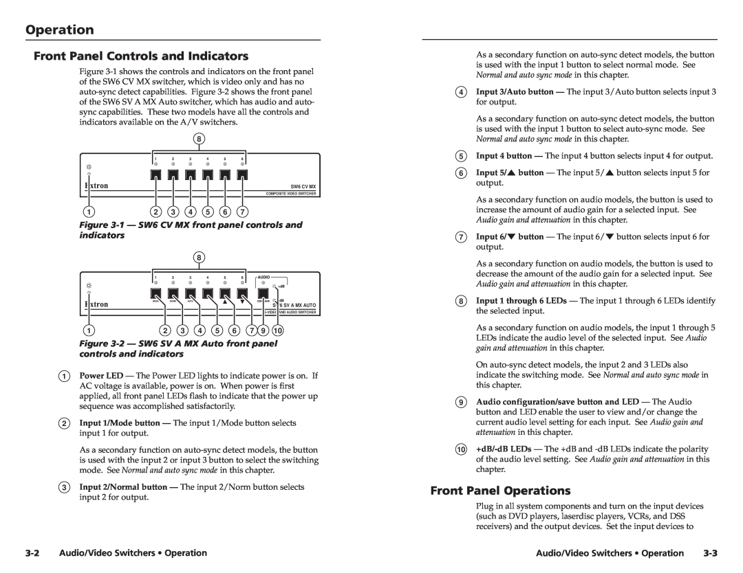
Figure 3-1 — SW6 CV MX front panel controls and indicators
8
MODE | NORM. | AUTO |
SW6 SV A MX AUTO
1 | 2 | 3 | 4 | 5 | 6 | 7 | 9 | 10 |
Figure 3-2 — SW6 SV A MX Auto front panel controls and indicators
1Power LED — The Power LED lights to indicate power is on. If AC voltage is available, power is on. When power is first applied, all front panel LEDs flash to indicate that the power up sequence was accomplished satisfactorily.
2Input 1/Mode button — The input 1/Mode button selects input 1 for output.
As a secondary function on
3Input 2/Normal button — The input 2/Norm button selects input 2 for output.
As a secondary function on
4Input 3/Auto button — The input 3/Auto button selects input 3 for output.
As a secondary function on
5Input 4 button — The input 4 button selects input 4 for output.
6Input 5/![]() button — The input 5/
button — The input 5/![]() button selects input 5 for output.
button selects input 5 for output.
As a secondary function on audio models, the button is used to increase the amount of audio gain for a selected input. See Audio gain and attenuation in this chapter.
7Input 6/![]() button — The input 6/
button — The input 6/![]() button selects input 6 for output.
button selects input 6 for output.
As a secondary function on audio models, the button is used to decrease the amount of the audio gain for a selected input. See Audio gain and attenuation in this chapter.
8Input 1 through 6 LEDs — The input 1 through 6 LEDs identify the selected input.
As a secondary function on audio models, the input 1 through 5 LEDs indicate the audio level of the selected input. See Audio gain and attenuation in this chapter.
On
9Audio configuration/save button and LED — The Audio button and LED enable the user to view and/or change the current audio level setting for each input. See Audio gain and attenuation in this chapter.
10
Front Panel Operations
Plug in all system components and turn on the input devices (such as DVD players, laserdisc players, VCRs, and DSS receivers) and the output devices. Set the input devices to
Audio/Video Switchers • Operation | Audio/Video Switchers • Operation |