Installation, cont’d
Audio models
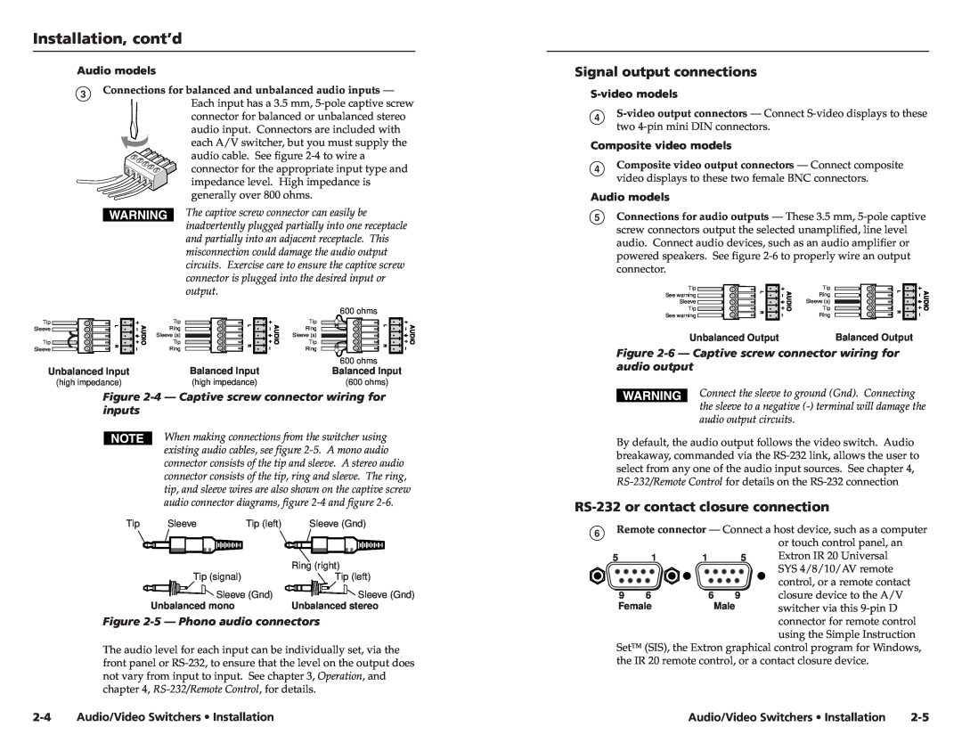
3Connections for balanced and unbalanced audio inputs —
Each input has a 3.5 mm,
The captive screw connector can easily be inadvertently plugged partially into one receptacle and partially into an adjacent receptacle. This misconnection could damage the audio output circuits. Exercise care to ensure the captive screw connector is plugged into the desired input or output.
Signal output connections
4
Composite video models
4Composite video output connectors — Connect composite video displays to these two female BNC connectors.
Audio models
5Connections for audio outputs — These 3.5 mm,
Tip | Tip |
See warning | Ring |
Sleeve | Sleeve (s) |
Tip
Sleeve
Tip
Sleeve
Unbalanced Input
(high impedance)
Tip
Ring
Sleeve (s)
Tip
Ring
Balanced Input
(high impedance)
600 ohms
Tip
Ring
Sleeve (s)
Tip
Ring
600ohms
Balanced Input
(600 ohms)
Tip | Tip |
See warning | Ring |
Unbalanced Output | Balanced Output |
Figure 2-6 — Captive screw connector wiring for audio output
Figure 2-4 — Captive screw connector wiring for inputs
When making connections from the switcher using existing audio cables, see figure
Tip | Sleeve | Tip (left) | Sleeve (Gnd) |
|
|
| Ring (right) |
| Tip (signal) |
| Tip (left) |
| Sleeve (Gnd) | Sleeve (Gnd) | |
| Unbalanced mono |
| Unbalanced stereo |
Figure 2-5 — Phono audio connectors
The audio level for each input can be individually set, via the front panel or
Connect the sleeve to ground (Gnd). Connecting the sleeve to a negative
By default, the audio output follows the video switch. Audio breakaway, commanded via the
RS-232 or contact closure connection
6Remote connector — Connect a host device, such as a computer or touch control panel, an
5 | 1 | 1 | 5 | Extron IR 20 Universal |
|
|
|
| SYS 4/8/10/AV remote |
|
|
|
| control, or a remote contact |
9 | 6 | 6 | 9 | closure device to the A/V |
Female | Male | switcher via this | ||
|
|
|
| connector for remote control |
|
|
|
| using the Simple Instruction |
Set™ (SIS), the Extron graphical control program for Windows, the IR 20 remote control, or a contact closure device.
Audio/Video Switchers • Installation | Audio/Video Switchers • Installation |