YCS SW2 specifications
The Extron YCS SW2 is a state-of-the-art analog audio matrix switcher designed to address the complex audio switching needs within professional AV environments. As part of Extron’s commitment to innovation in AV technology, the YCS SW2 offers a robust solution for seamless audio management in various settings, including educational institutions, corporate boardrooms, and event spaces.One of the standout features of the YCS SW2 is its ability to accommodate multiple audio sources. The switcher supports up to 12 inputs, enabling users to connect various devices such as microphones, mixers, and media players. This flexibility ensures that users can easily integrate a wide range of audio sources into their setups, facilitating dynamic presentations and discussions.
The YCS SW2 utilizes Extron’s proprietary technology known as the "YCS" or "Yearless Configuration System," which allows for extensive control features. With this system, users can define and customize audio routing profiles, ensuring that the right audio sources are directed to the appropriate outputs at any given time. This level of customization is essential for environments where audio requirements frequently change or when specific routing configurations are necessary for particular events.
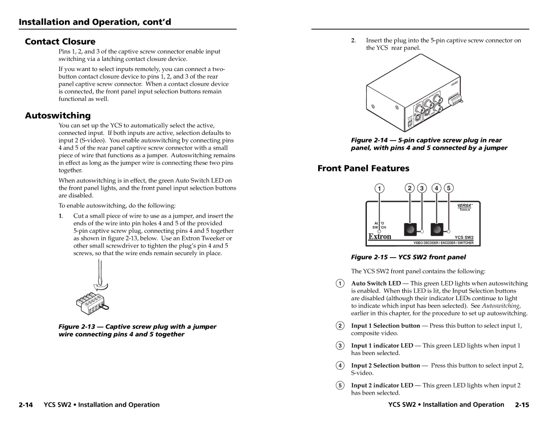
Another significant characteristic of the YCS SW2 is its user-friendly interface. The switcher is equipped with an intuitive control panel, featuring tactile buttons and a clear LED indication system. This design ensures that operators can quickly and easily navigate through the switcher's functionality, minimizing the learning curve and enhancing operational efficiency.
Audio performance is further bolstered by the YCS SW2’s integrated audio processing capabilities. The switcher includes features such as adjustable gain control, equalization, and other signal enhancements that can optimize the audio output quality. This ensures that audio signals remain clear and professional-grade, whether the context is a presentation, a lecture, or a live event.
In terms of connectivity, the YCS SW2 provides convenient options for both analog and digital standards, ensuring compatibility with a wide range of existing AV equipment. This flexibility in connectivity options simplifies integration, making it easier for users to incorporate the switcher into their current infrastructure.
In conclusion, the Extron YCS SW2 represents a remarkable advancement in analog audio switching technology, combining versatile input options, an intuitive control interface, and advanced audio processing capabilities. These features collectively enhance its functionality, making it a vital tool for professionals aiming to deliver exceptional audio experiences in diverse AV environments. Whether for educational use or corporate applications, the YCS SW2 is poised to meet the demands of modern audio management with reliability and ease.

