Contents
Limited Warranty | 2 | Changing Collets | 9 |
30 Day Money Back Guarantee | 2 | Setting the Plunge Depth | 10 |
1+2 Limited Warranty | 2 | Offset from a Surface | 10 |
Conditions of 1+2 Limited Warranty | 2 | By Router Bit Profile | 10 |
Repairs | 2 | Changing Baseplates | 11 |
Returns | 2 | Installing Template Guides and Chip Deflector .. | 11 |
Liability Statement | 2 | Basic Routing | 12 |
Proprietary Notice | 2 | Feed Direction Rules | 12 |
About This Manual | 3 | Fixed Depth Routing | 12 |
Tool Symbols | 3 | Fixed Depth Using the Turret Latch | 13 |
General Power Tool Safety Warnings | 4 | Plunge Routing | 13 |
Work Area Safety | 4 | Plough Cuts | 13 |
Electrical Safety | 4 | Using a Template Guide | 14 |
Personal Safety | 4 | Advanced Routing Techniques | 14 |
Power Tool Use and Care | 4 | 14 | |
Service | 5 | 14 | |
Specific Safety Rules for Routers | 5 | 15 | |
Respiratory Exposure Safety Warnings | 5 | 15 | |
Tool Description | 5 | 15 | |
Technical Specifications | 5 | Precision Routing | 16 |
Intended Use | 6 | Tips for Successful Routing | 17 |
Overview | 6 | Chipping and Tearout | 17 |
Power Controls | 7 | Chatter | 17 |
Router Speed and Feed Rate | 7 | Router Control | 17 |
Dust Collection | 7 | 18 | |
Plunge Components | 8 | What is | 18 |
Depth Stop Turret | 8 | Notes and Tips | 18 |
Turret Latching Lever | 8 | Accessories | 19 |
Fine Adjustment Dial | 8 | Guide Rail Attachment | 19 |
Plunge Depth Gauge | 8 | Edge Guide | 20 |
Plunge Lock Knob | 8 | Systainer (System Container) | 21 |
Depth Stop Locking Lever and Post | 8 | Troubleshooting | 22 |
Basic Operation | 9 | Maintenance | 23 |
Changing Router Bits | 9 | Routine Maintenance | 23 |
About This Manual
Save These Instructions
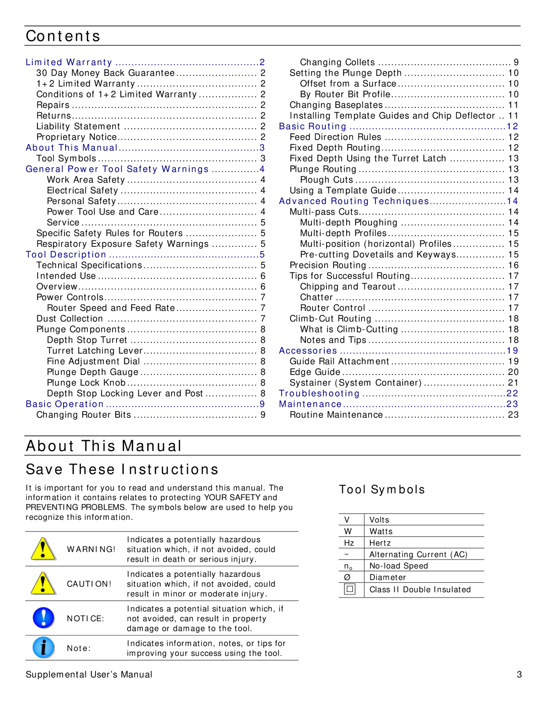
It is important for you to read and understand this manual. The information it contains relates to protecting YOUR SAFETY and PREVENTING PROBLEMS. The symbols below are used to help you recognize this information.
| Indicates a potentially hazardous | |
WARNING! | situation which, if not avoided, could | |
| result in death or serious injury. | |
|
| |
| Indicates a potentially hazardous | |
CAUTION! | situation which, if not avoided, could | |
| result in minor or moderate injury. | |
|
| |
| Indicates a potential situation which, if | |
NOTICE: | not avoided, can result in property | |
| damage or damage to the tool. | |
|
| |
Note: | Indicates information, notes, or tips for | |
improving your success using the tool. | ||
| ||
|
|
Tool Symbols
V | Volts |
W | Watts |
Hz | Hertz |
~ | Alternating Current (AC) |
no | |
Ø | Diameter |
| Class II Double Insulated |
|
|
Supplemental User’s Manual | 3 |
