| Driver Manual |
Read/ | COMMAND NAME |
Write/ |
|
Both |
|
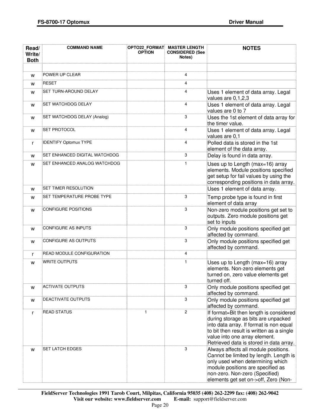
wPOWER UP CLEAR
wRESET
wSET
OPTO22_FORMAT | MASTER LENGTH | NOTES |
OPTION | CONSIDERED (See |
|
| Notes) |
|
4
4
4Uses 1 element of data array. Legal values are 0,1,2,3
w | SET WATCHDOG DELAY |
| 4 | Uses 1 element of data array. Legal |
|
|
|
| values are 0 to 7 |
w | SET WATCHDOG DELAY (Analog) |
| 3 | Uses the 1st element of data array for |
|
|
|
| the timer value. |
w | SET PROTOCOL |
| 4 | Uses 1 element of data array. Legal |
|
|
|
| values are 0,1 |
r | IDENTIFY Optomux TYPE |
| 4 | Polled data is stored in the 1st |
|
|
|
| element of the data array. |
w | SET ENHANCED DIGITAL WATCHDOG |
| 3 | Delay is found in data array. |
w | SET ENHANCED ANALOG WATCHDOG |
| 1 | Uses up to Length (max=16) array |
|
|
|
| elements. Module positions specified |
|
|
|
| get setup for fail values by using the |
|
|
|
| corresponding positions in data array. |
w | SET TIMER RESOLUTION |
|
| Uses 1 element of data array. |
w | SET TEMPERATURE PROBE TYPE |
| 3 | Temp probe type is found in first |
|
|
|
| element of data array |
w | CONFIGURE POSITIONS |
| 3 | |
|
|
|
| outputs. Zero module positions get |
|
|
|
| set to inputs |
w | CONFIGURE AS INPUTS |
| 3 | Only module positions specified get |
|
|
|
| affected by command. |
w | CONFIGURE AS OUTPUTS |
| 3 | Only module positions specified get |
r | READ MODULE CONFIGURATION |
| 4 | affected by command. |
|
| |||
w | WRITE OUTPUTS |
| 1 | Uses up to Length (max=16) array |
|
|
|
| elements. |
|
|
|
| turned on, zero value elements get |
|
|
|
| turned off. |
w | ACTIVATE OUTPUTS |
| 3 | Only module positions specified get |
|
|
|
| affected by command. |
w | DEACTIVATE OUTPUTS |
| 3 | Only module positions specified get |
|
|
|
| affected by command. |
r | READ STATUS | 1 | 2 | If format=Bit then length is considered |
|
|
|
| during storage as bits are unpacked |
|
|
|
| into data array. If format is non equal |
|
|
|
| to bit then result is written as a single |
|
|
|
| value into one array element. |
|
|
|
| Retrieved data is stored in data array. |
w | SET LATCH EDGES |
| 3 | Always affects all module positions. |
|
|
|
| Cannot be limited by length. Length is |
only used when determining which module positions are specified as
FieldServer Technologies 1991 Tarob Court, Milpitas, California 95035 (408)
Visit our website: www.fieldserver.com
Page 20