Driver Manual |
3 Hardware Connections
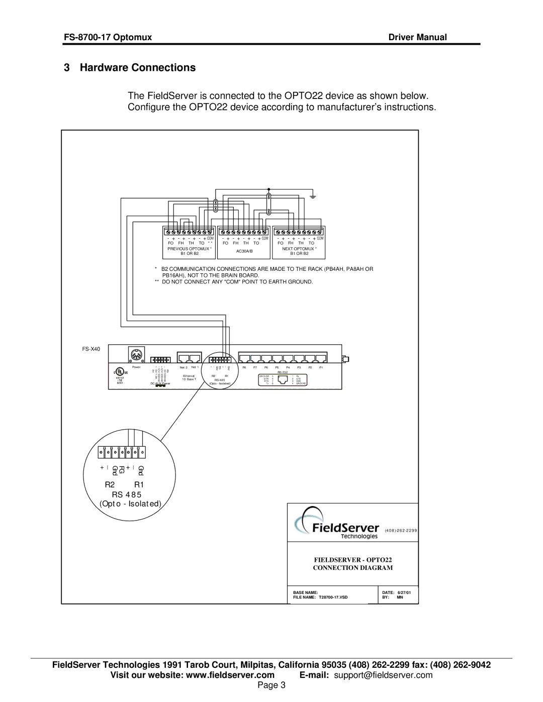
The FieldServer is connected to the OPTO22 device as shown below.
Configure the OPTO22 device according to manufacturer’s instructions.
- + - + - + | - + COM | - + - + - + | - + COM | ||||
FO | FH | TH | TO * * | FO | FH | TH | TO |
PREVIOUS OPTOMUX * | AC30A/B | |
B1 OR B2 | ||
|
- + - + - + - + COM
FO FH TH TO
NEXT OPTOMUX *
B1 OR B2
*B2 COMMUNICATION CONNECTIONS ARE MADE TO THE RACK (PB4AH, PA8AH OR PB16AH), NOT TO THE BRAIN BOARD.
**DO NOT CONNECT ANY "COM" POINT TO EARTH GROUND.
FS-X40
Power
_ + _ + | ||||
5V 0V | 12V | 12V | 5V | FG |
1.5A | 500mA | 500mA | 500mA |
|
DC AUX Power
Net 2 Net 1
Et hernet 10 Base T
Gnd _ + FG Gnd _ +
R2 R1
RS 485
(Opto - Isolated)
P8 | P7 | P6 |
| P5 | P4 |
| P3 | P2 | P1 |
|
|
|
| RS 232 |
|
|
|
| |
|
| GROUND | 5 | 8 | 1 | 1 | Rx |
|
|
|
| DTR | 6 |
|
| 2 | CTS |
|
|
|
| RTS | 7 |
|
| 3 | DSR |
|
|
|
| Tx | 8 |
|
| 4 | GROUND |
|
|
| _ | _ |
+ | + FG Gnd | Gnd |
R2 | R1 | |
RS 4 8 5 (Opt o - Isolat ed)
(4 0 8
FIELDSERVER - OPTO22
CONNECTION DIAGRAM
BASE NAME:
FILE NAME:
DATE: 6/27/01
BY: MN
FieldServer Technologies 1991 Tarob Court, Milpitas, California 95035 (408)
Visit our website: www.fieldserver.com
Page 3