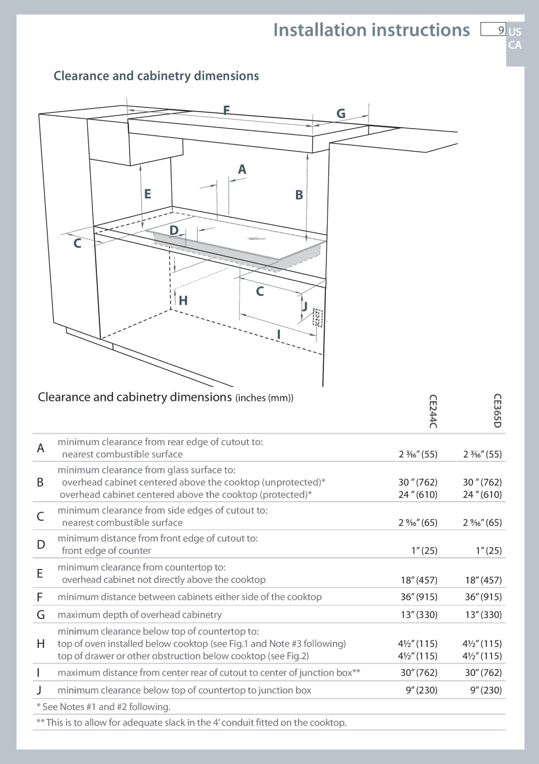
CE365D, CE244C specifications
Fisher & Paykel is renowned for its innovative approach to kitchen appliances, and their built-in electric ovens, CE244C and CE365D, exemplify this commitment to quality and design. Both models provide exceptional functionality while incorporating modern aesthetics, making them a great addition to any kitchen.The CE244C is a compact oven designed for versatile cooking. With a capacity of 44 liters, it is ideal for smaller spaces or culinary enthusiasts who prefer a streamlined cooking experience. This model features five cooking functions, including Bake, Grill, Fan Bake, and Self-Clean. The fan bake option ensures even heat distribution, leading to perfectly cooked meals. Moreover, the oven boasts an intuitive control panel, allowing users to easily select cooking modes and adjust temperatures with precision.
In contrast, the CE365D offers a larger capacity of 60 liters, catering to families or those who enjoy entertaining. This oven includes a generous array of cooking functions, including a steam mode that enhances moisture retention in dishes, resulting in succulent roasts and perfectly baked breads. Both models are equipped with a self-cleaning function, ensuring that maintenance becomes a hassle-free task. This feature utilizes high heat to burn off food residue, allowing homeowners to focus on cooking rather than cleaning.
One of the standout technologies in both models is the ActiveVent system, which optimizes humidity within the oven. This not only improves cooking outcomes but also allows for a wider variety of cooking techniques. The intuitive touch controls further enhance user experience, providing clear feedback and easy navigation through settings.
Both ovens are designed with safety in mind, featuring cool-to-touch doors and internal temperature sensors that prevent overheating. The interior surfaces are crafted from durable materials, ensuring longevity and easy cleaning.
Overall, the Fisher & Paykel CE244C and CE365D ovens represent a perfect blend of style and functionality. With their advanced cooking technologies, easy-to-use features, and thoughtful design, they cater to both everyday cooking needs and gourmet culinary adventures. Whether you are a novice home cook or a seasoned chef, these ovens provide the tools necessary to elevate your culinary creations.

