Installation instructions 17
Installation to Natural gas
Installation to Natural Gas must conform to the Code of Practice, etc. The supply pressure for Natural Gas is 20 mbar.
Installation to Liquid Petroleum gas
This appliance must only be connected to LPG after an LPG conversion kit has been fitted. The installation must conform to the relevant British Standards.
Important!
Only a suitably qualified and registered person may convert the appliance to a different gas type. When using Butane gas a supply pressure of 28
When using Propane gas a supply pressure of 37 mbar is required.
Notes:
Flexible hoses can be used where the sited ambient temperature of the hose does not exceed 70°C. These hoses must be manufactured in accordance with BS669 part 1 and be of the correct construction for the type of gas being used.
Gas hoses designed for natural gas MUST NOT be used for supplying LPG gas (LPG gas hoses can be identified by a either a red band or stripe on the rubber outer coating of the hose).
The hose should not be crushed or trapped or be in contact with sharp or abrasive edges. It should also not be subjected to corrosion by acidic cleansing agents.
To connect the gas supply:
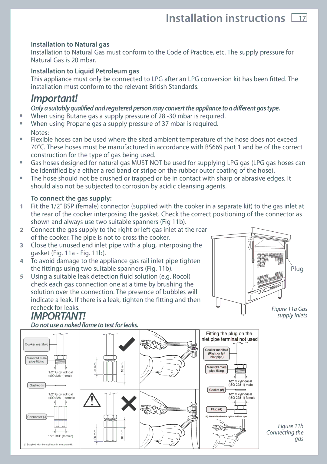
1Fit the 1/2” BSP (female) connector (supplied with the cooker in a separate kit) to the gas inlet at the rear of the cooker interposing the gasket. Check the correct positioning of the connector as shown and always use two suitable spanners (Fig 11b).
2Connect the gas supply to the right or left gas inlet at the rear
of the cooker. The pipe is not to cross the cooker.
3 Close the unused end inlet pipe with a plug, interposing the gasket (Fig. 11a - Fig. 11b).
4 To avoid damage to the appliance gas rail inlet pipe tighten the fittings using two suitable spanners (Fig. 11b).
5 Using a suitable leak detection fluid solution (e.g. Rocol) check each gas connection one at a time by brushing the solution over the connection. The presence of bubbles will indicate a leak. If there is a leak, tighten the fitting and then recheck for leaks.
IMPORTANT!
Do not use a naked flame to test for leaks.
Cooker manifold
Manifold male ![]() pipe fitting
pipe fitting ![]()
![]()
1/2” G cylindrical (ISO
Gasket (*)
1/2” G cylindrical (ISO
Connector (*)
1/2” BSP (female)
(*) Supplied with the appliance in a separate kit.
|
|
| 10 mm |
|
20 mm |
|
|
| |
|
|
|
|
|
|
|
|
|
|
|
|
|
|
|
|
|
|
|
|
|
|
|
|
|
|
|
|
|
|
|
|
|
|
|
|
|
|
|
|
|
20 mm |
|
|
|
| 10 mm |
|
|
|
|
|
|
|
|