SU4/UF2
BASIC ANTENNA/CABLE CONNECTIONS
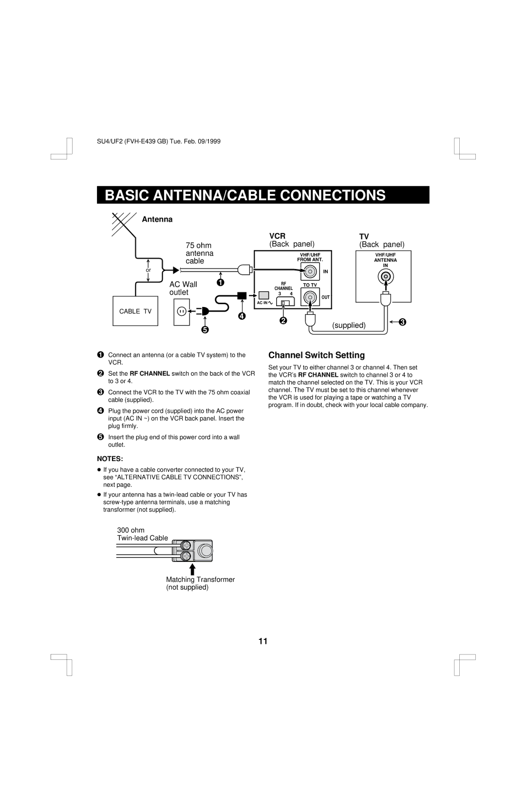
Antenna
75 ohm antenna cable
VCR |
|
(Back | panel) |
| VHF/UHF |
| FROM ANT. |
TV
(Back panel)
VHF/UHF
ANTENNA
IN
or
CABLE TV
AC Wall | 1 | |||||||||
outlet |
| |||||||||
|
|
|
|
|
|
|
|
|
|
|
|
|
|
|
|
|
|
|
|
|
|
|
|
|
|
|
|
|
|
|
|
|
|
|
|
|
|
|
|
|
|
|
|
|
|
|
|
|
|
|
|
|
|
|
5
|
| IN |
| RF | TO TV |
| CHANNEL | |
| 3 | 4 |
|
| OUT |
| AC IN |
|
4 | 2 |
|
|
| |
(supplied) 3
1Connect an antenna (or a cable TV system) to the VCR.
2Set the RF CHANNEL switch on the back of the VCR to 3 or 4.
3Connect the VCR to the TV with the 75 ohm coaxial cable (supplied).
4Plug the power cord (supplied) into the AC power input (AC IN ~) on the VCR back panel. Insert the plug firmly.
5Insert the plug end of this power cord into a wall outlet.
NOTES:
œIf you have a cable converter connected to your TV, see “ALTERNATIVE CABLE TV CONNECTIONS”, next page.
œIf your antenna has a
300 ohm
Channel Switch Setting
Set your TV to either channel 3 or channel 4. Then set the VCR's RF CHANNEL switch to channel 3 or 4 to match the channel selected on the TV. This is your VCR channel. The TV must be set to this channel whenever the VCR is used for playing a tape or watching a TV program. If in doubt, check with your local cable company.
Matching Transformer (not supplied)
11