Quest Ab Lounge XL System specifications
The Fitness Quest Quest Ab Lounge XL System is a premier exercise equipment designed to target the abdominal muscles effectively while providing a comfortable and efficient workout experience. With its innovative design and advanced technology, the Ab Lounge XL is built to accommodate users of various fitness levels, making it an excellent choice for anyone aiming to enhance their core strength.One of the standout features of the Ab Lounge XL is its unique reclining design. The supportive, padded lounge chair elevates your upper body and allows users to perform crunches without straining the neck or back. This ergonomic approach prevents common workout injuries, enabling individuals to focus on their ab exercises comfortably. The wider seat and higher backrest provide additional support and stability, ensuring optimal comfort during each session.
The Ab Lounge XL incorporates a smooth, gliding motion that enhances the effectiveness of your ab workouts. The rotating motion engages multiple muscle groups, emphasizing the upper and lower abs while also targeting the obliques. This full-range motion allows users to perform various exercises, ensuring a comprehensive core workout with every use.
In terms of technology, the Ab Lounge XL features a built-in, adjustable resistance system. This allows users to customize their workout intensity to suit individual fitness levels. Whether you're a beginner or an advanced athlete, the ability to tweak resistance levels helps you progress at your own pace and continually challenge your muscles.
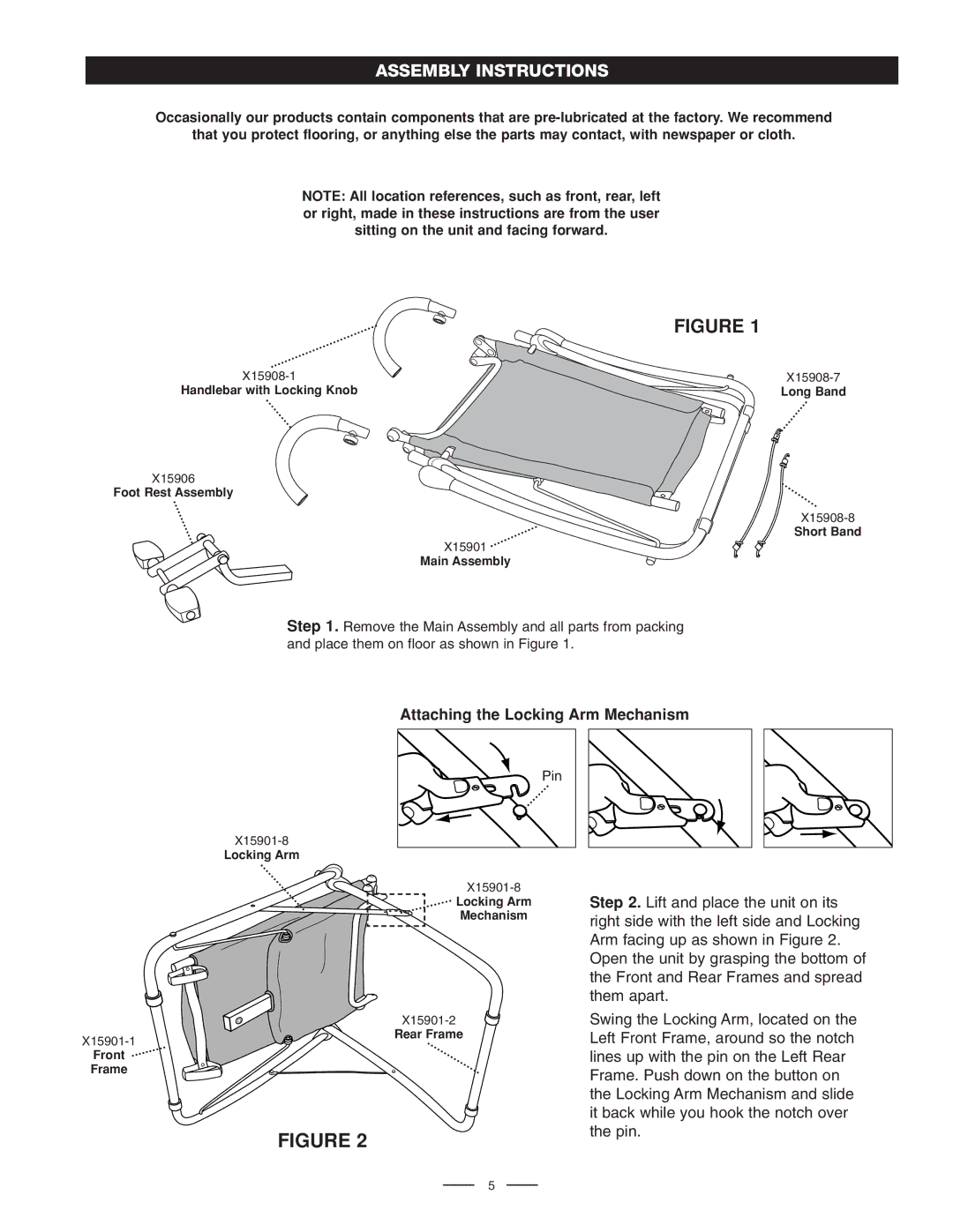
The Ab Lounge XL's assembly is straightforward, making it accessible for users who may be new to fitness equipment. Its compact design ensures that it can fit in various home environments, making it a versatile addition to any workout space. Additionally, its lightweight construction allows for easy storage and repositioning when not in use.
To further enhance the workout experience, the Ab Lounge XL comes with workout DVDs and a nutrition guide, allowing users to complement their physical training with helpful dietary tips. This holistic approach to fitness ensures that users can achieve their goals more efficiently.
In summary, the Fitness Quest Quest Ab Lounge XL System is a well-engineered piece of equipment specifically targeting abdominal workouts. With its ergonomic design, adjustable resistance levels, and supported functionality, it's an excellent investment for anyone looking to improve their core strength in a safe and effective manner.

