Installing SFP transceivers | Hardware installation |
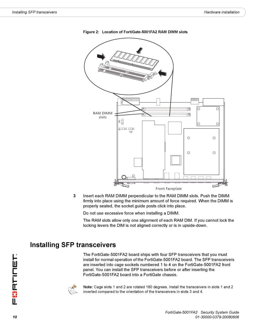
Figure 2: Location of FortiGate-5001FA2 RAM DIMM slots
RAM DIMM
slots
JP1 JP2![]()
![]()
![]()
![]()
![]()
JP3
Front Faceplate
3Insert each RAM DIMM perpendicular to the RAM DIMM slots. Push the DIMM firmly into place using the minimum amount of force required. When the DIMM is properly seated, the socket guide posts click into place.
Do not use excessive force when installing a DIMM.
The RAM slots allow only one alignment of each RAM DIM. If you cannot lock the locking levers the DIM is not aligned correctly or is in
Installing SFP transceivers
The
Note: Cage slots 1 and 2 are rotated 180 degrees. Install the transceivers in slots 1 and 2 inverted compared to the orientation of the transceivers in slots 3 and 4.
| |
10 |