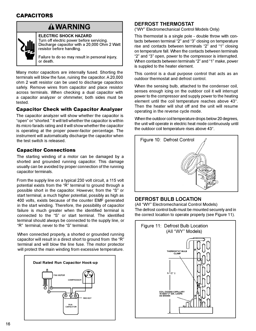
CAPACITORS

WARNING

ELECTRIC SHOCK HAZARD

Turn off electric power before servicing. Discharge capacitor with a 20,000 Ohm 2 Watt resistor before handling.

Failure to do so may result in personal injury, or death.

Many motor capacitors are internally fused. Shorting the terminals will blow the fuse, ruining the capacitor. A 20,000 ohm 2 watt resistor can be used to discharge capacitors safely. Remove wires from capacitor and place resistor across terminals. When checking a dual capacitor with a capacitor analyzer or ohmmeter, both sides must be tested.

Capacitor Check with Capacitor Analyzer

The capacitor analyzer will show whether the capacitor is “open” or “shorted.” It will tell whether the capacitor is within its micro farads rating and it will show whether the capacitor is operating at the proper power-factor percentage. The instrument will automatically discharge the capacitor when the test switch is released.

Capacitor Connections

The starting winding of a motor can be damaged by a shorted and grounded running capacitor. This damage usually can be avoided by proper connection of the running capacitor terminals.

From the supply line on a typical 230 volt circuit, a 115 volt potential exists from the “R” terminal to ground through a possible short in the capacitor. However, from the “S” or start terminal, a much higher potential, possibly as high as 400 volts, exists because of the counter EMF generated in the start winding. Therefore, the possibility of capacitor failure is much greater when the identified terminal is connected to the “S” or start terminal. The identified terminal should always be connected to the supply line, or “R” terminal, never to the “S” terminal.

When connected properly, a shorted or grounded running capacitor will result in a direct short to ground from the “R” terminal and will blow the line fuse. The motor protector will protect the main winding from excessive temperature.

Dual Rated Run Capacitor Hook-up

F C H

DEFROST THERMOSTAT

(“WY” Electromechanical Control Models Only)

This thermostat is a single pole - double throw with con- tacts between terminal “2” and “3” closing on temperature rise and contacts between terminals “2” and “1” closing on temperature fall. When the contacts between terminals “2” and “3” open, power to the compressor is interrupted. When contacts between terminals “2” and “1” make, power is suppled to the heater element.

This control is a dual purpose control that acts as an outdoor thermostat and defrost control.

When the sensing bulb, attached to the condenser coil, senses enough icing on the outdoor coil it will interrupt power to the compressor and supply power to the heating element until the coil temperature reaches above 43°. Then the heater will shut off and the unit will resume operating in the reverse cycle mode.

When the outdoor coil temperature drops below 20 degrees, the unit will operate in electric heat mode continuously until the outdoor coil temperature rises above 43°.

Figure 10: Defrost Control

DEFROST BULB LOCATION

(All “WY” Electromechanical Control Models)

The defrost control bulb must be mounted securely and in the correct location to operate properly (see Figure 11).

Figure 11: Defrost Bulb Location

(All “WY” Models)

16

Page 18
Image 18
Friedrich 2008, 2009 Capacitors, Defrost Thermostat, Defrost Bulb Location, Capacitor Check with Capacitor Analyzer

2009, 2008 specifications

Friedrich 2008 and 2009 represent significant advancements in heating and cooling technology, particularly in the realm of air conditioning systems. Friedrich is known for producing robust and efficient HVAC solutions tailored for both residential and commercial applications. These models are particularly noteworthy for their innovative features and energy-efficient technologies that enhance user comfort and lower operational costs.

One of the main characteristics of the Friedrich 2008 and 2009 models is their emphasis on energy efficiency. Both units are designed to meet or exceed Energy Star standards, which indicates that they use less energy compared to standard models, contributing to greener living solutions. The incorporation of efficient compressors and high SEER (Seasonal Energy Efficiency Ratio) ratings ensures that users save money on their electricity bills while enjoying optimal cooling performance.

The units also feature advanced inverter technology, which allows for variable speed operation. This means that the system can adjust its cooling capacity based on the current temperature needs, resulting in more consistent comfort while reducing wear and tear on the equipment. Additionally, the inverter technology operates more quietly compared to traditional systems, making these models suitable for both home environments and commercial settings.

Friedrich 2008 and 2009 also provide users with enhanced control options. The inclusion of smart technology and Wi-Fi connectivity allows for remote monitoring and temperature adjustments via smartphones or tablets. Users can create schedules, set temperature preferences, and receive maintenance alerts, contributing to a more user-friendly experience.

Moreover, these models are designed with robust construction, featuring durable materials that withstand various weather conditions. Their compact footprint and sleek design make them suitable for window installation, while an array of sizes accommodates spaces of different dimensions.

Additionally, the air filtration systems in Friedrich 2008 and 2009 units improve indoor air quality. They effectively capture dust, allergens, and other particulates, ensuring a healthier environment for occupants.

In summary, Friedrich 2008 and 2009 models stand out for their energy efficiency, innovative inverter technology, smart controls, and robust construction. With a focus on user comfort and environmental responsibility, these models provide reliable solutions for effective heating and cooling in diverse applications.