PTAC specifications
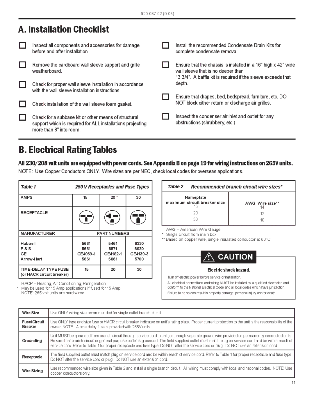
Friedrich PTAC (Packaged Terminal Air Conditioner) units are a popular choice for heating and cooling in commercial and residential spaces, thanks to their efficient design and reliable performance. Friedrich, a company with a long-standing reputation in the HVAC industry, offers a range of PTAC units characterized by advanced features and technologies that set them apart from traditional cooling systems.One of the main features of Friedrich PTAC units is their high energy efficiency. Many of their models are Energy Star certified, which means they meet the stringent energy efficiency guidelines set by the U.S. Environmental Protection Agency. This efficiency translates into lower energy costs for users and reduced environmental impact, making them an excellent choice for energy-conscious consumers.
Friedrich PTAC units are equipped with advanced technologies that enhance their functionality. For instance, many units come with a built-in Wi-Fi option, enabling remote control through mobile devices. This feature allows users to monitor and adjust temperature settings, schedules, and modes from anywhere, providing convenience and ensuring energy is not wasted when spaces are unoccupied.
The design of Friedrich PTAC units also emphasizes ease of installation and maintenance. These units are designed to fit into existing wall sleeves, making replacement straightforward without significant structural modifications. Furthermore, their ease of access for servicing ensures that maintenance tasks can be performed quickly, reducing downtime and improving longevity.
Another key characteristic of Friedrich PTAC units is their robust construction. Built to withstand varying conditions, these units feature durable materials that ensure long-term reliability. Many models incorporate advanced sound-dampening technology, creating a quieter operation that enhances comfort, especially in residential applications.
Friedrich’s commitment to innovation is evident in its product line, offering various options to meet different climate requirements and user preferences. The units can provide both heating and cooling, making them versatile for year-round use. Additionally, they are available in various BTU capacities, allowing customers to select the appropriate model for their specific space needs.
Overall, Friedrich PTAC units are recognized for their efficiency, technological advancements, ease of installation, and sturdy design, making them an excellent choice for both commercial and residential applications where reliable climate control is needed.

