MB15F74UV
•Prescaler Data Setting
Divide ratio |
|
| SW = “1” | SW = “0” | ||
|
|
|
|
|
| |
Prescaler divide ratio |
| 32/33 | 64/65 | |||
|
|
|
|
|
| |
Prescaler divide ratio |
| 64/65 | 128/129 | |||
|
|
|
|
|
| |
• Charge Pump Current Setting |
|
|
| |||
Current value |
| CS |
|
|
| |
|
|
|
|
|
|
|
±6.0 mA |
| 1 |
|
|
|
|
|
|
|
|
|
|
|
±1.5 mA |
| 0 |
|
|
|
|
|
|
|
|
|
|
|
•LD/fout output Selectable Bit Setting
LD/fout pin state | LDS | T1 | T2 | ||
|
|
|
|
|
|
|
|
| 0 | 0 | 0 |
|
|
|
|
| |
LD output |
| 0 | 1 | 0 | |
|
|
|
|
|
|
|
|
| 0 | 1 | 1 |
|
|
|
|
|
|
|
| frIF | 1 | 0 | 0 |
|
|
|
|
|
|
fout |
| frRF | 1 | 1 | 0 |
output |
| fpIF | 1 | 0 | 1 |
|
|
|
|
|
|
|
| fpRF | 1 | 1 | 1 |
|
|
|
|
|
|
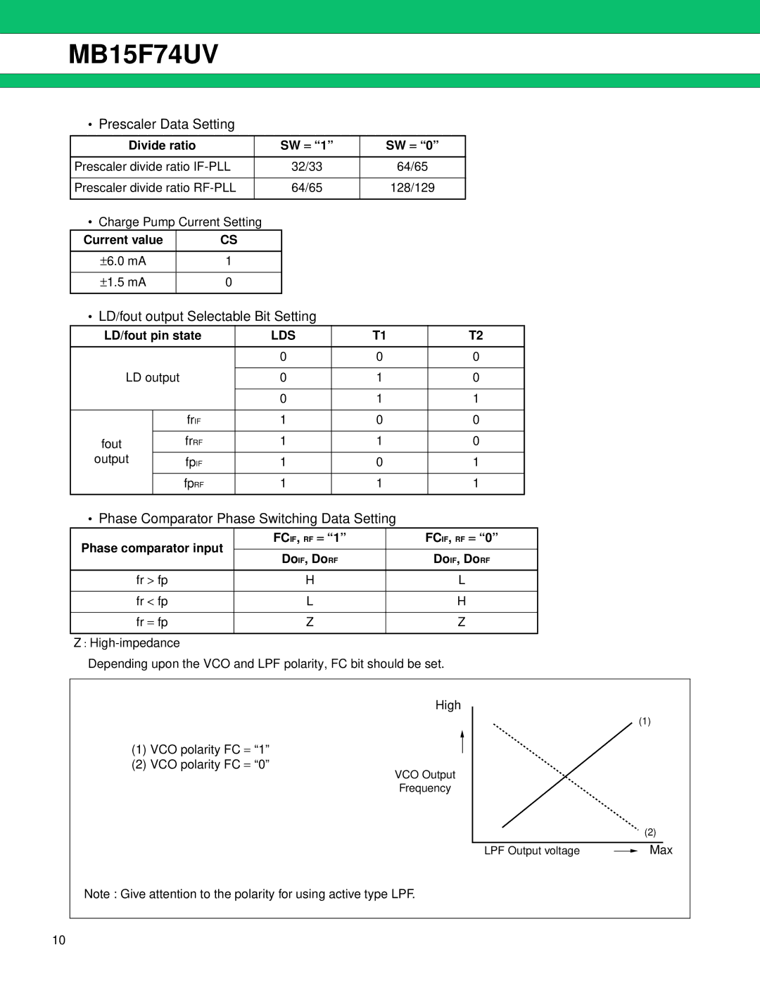
•Phase Comparator Phase Switching Data Setting
Phase comparator input | FCIF, RF = “1” | FC IF, RF = “0” | |
|
| ||
DoIF, DoRF | DoIF, DoRF | ||
| |||
|
|
| |
fr > fp | H | L | |
|
|
| |
fr < fp | L | H | |
|
|
| |
fr = fp | Z | Z | |
|
|
| |
Z : |
|
|
Depending upon the VCO and LPF polarity, FC bit should be set.
High
(1)
(1)VCO polarity FC = “1”
(2)VCO polarity FC = “0”
VCO Output
Frequency
(2)
LPF Output voltage |
| Max |
|
Note : Give attention to the polarity for using active type LPF.
10