MB15F74UV
■FUNCTIONAL DESCRIPTION
1. Pulse swallow function
fVCO = [ (P ⋅ N) + A] ⋅ fOSC ⎟ R
fVCO : Output frequency of external voltage controlled oscillator (VCO)
P: Preset divide ratio of dual modulus prescaler (32 or 64 for
N : Preset divide ratio of binary
A : Preset divide ratio of binary
fOSC : Reference oscillation frequency (OSCIN input frequency)
R : Preset divide ratio of binary
2.Serial Data Input
The serial data is entered using three pins, Data pin, Clock pin, and LE pin. Programmable dividers of IF/RF- PLL sections, programmable reference dividers of
The serial data of binary data is entered through Data pin.
On rising edge of Clock, one bit of the serial data is transferred into the shift register. On a rising edge of load enable signal, the data stored in the shift register is transferred to one of latches depending upon the control bit data setting.
| The programmable | The programmable | The programmable | The programmable |
| reference counter | reference counter | counter and the swallow | counter and the swallow |
| for the | for the | counter for the | counter for the |
|
|
|
|
|
CN1 | 0 | 1 | 0 | 1 |
|
|
|
|
|
CN2 | 0 | 0 | 1 | 1 |
|
|
|
|
|
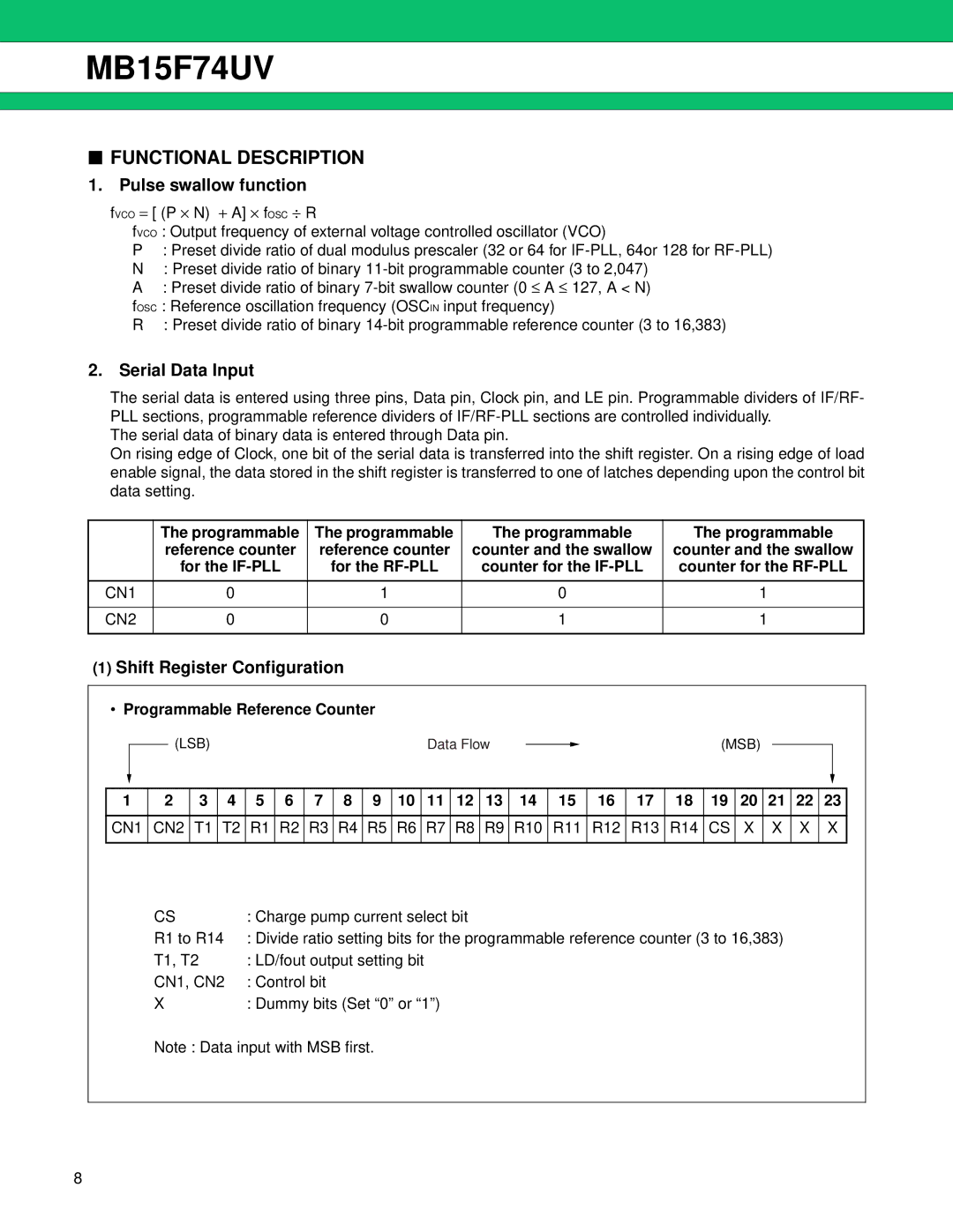
(1)Shift Register Configuration
•Programmable Reference Counter
(LSB)Data Flow ![]() (MSB)
(MSB)
1 | 2 | 3 | 4 | 5 | 6 | 7 | 8 | 9 | 10 | 11 | 12 | 13 | 14 | 15 | 16 | 17 | 18 | 19 | 20 | 21 | 22 | 23 |
|
|
|
|
|
|
|
|
|
|
|
|
|
|
|
|
|
|
|
|
|
|
|
CN1 | CN2 | T1 | T2 | R1 | R2 | R3 | R4 | R5 | R6 | R7 | R8 | R9 | R10 | R11 | R12 | R13 | R14 | CS | X | X | X | X |
|
|
|
|
|
|
|
|
|
|
|
|
|
|
|
|
|
|
|
|
|
|
|
CS | : Charge pump current select bit |
R1 to R14 | : Divide ratio setting bits for the programmable reference counter (3 to 16,383) |
T1, T2 | : LD/fout output setting bit |
CN1, CN2 | : Control bit |
X: Dummy bits (Set “0” or “1”)
Note : Data input with MSB first.
8