MB15F74UV
3. Power Saving Mode (Intermittent Mode Control Circuit)
Status | PS pin |
|
|
Normal mode | H |
|
|
Power saving mode | L |
|
|
The intermittent mode control circuit reduces the PLL power consumption.
By setting the PS pin low, the device enters into the power saving mode, reducing the current consumption. See the Electrical Characteristics chart for the specific value.
The phase detector output, Do, becomes high impedance.
For the dual PLL, the lock detector, LD, is as shown in the LD Output Logic table.
Setting the PS pin high, releases the power saving mode, and the device works normally.
The intermittent mode control circuit also ensures a smooth startup when the device returns to normal operation. When the PLL is returned to normal operation, the phase comparator output signal is unpredictable. This is because of the unknown relationship between the comparison frequency (fp) and the reference frequency (fr) which can cause a major change in the comparaor output, resulting in a VCO frequency jump and an increase in lockup time.
To prevent a major VCO frequency jump, the intermittent mode control circuit limits the magnitude of the error signal from the phase detector when it returns to normal operation.
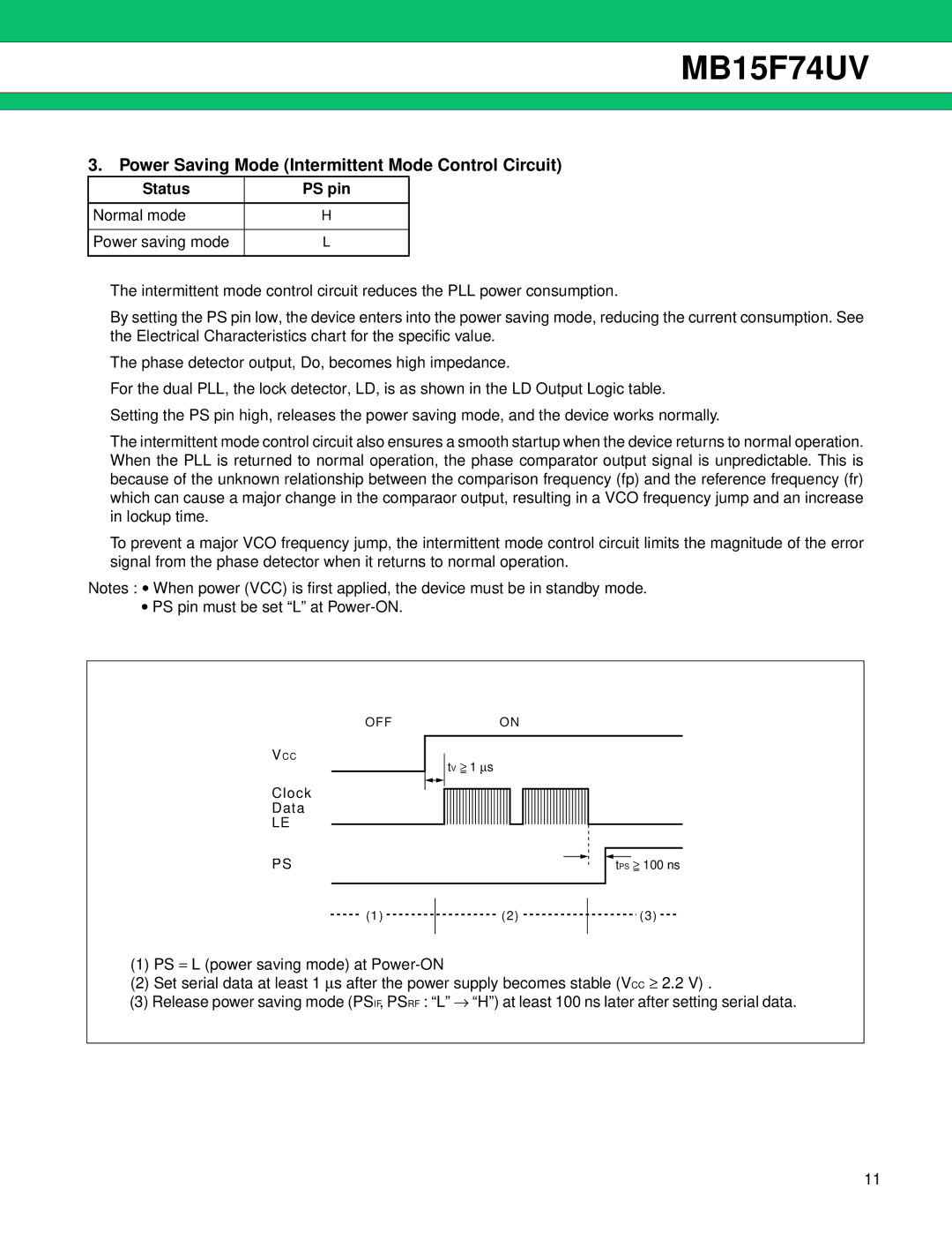
Notes : • When power (VCC) is first applied, the device must be in standby mode.
•PS pin must be set “L” at
OFF
VCC
Clock
Data
LE
PS
ON
tV ≥ 1 ∝s
tPS ≥ 100 ns
(1)
(2)
(3)
(1)PS = L (power saving mode) at
(2)Set serial data at least 1 ∝s after the power supply becomes stable (VCC ≥ 2.2 V) .
(3)Release power saving mode (PSIF, PSRF : “L” → “H”) at least 100 ns later after setting serial data.
11