MB15F74UV
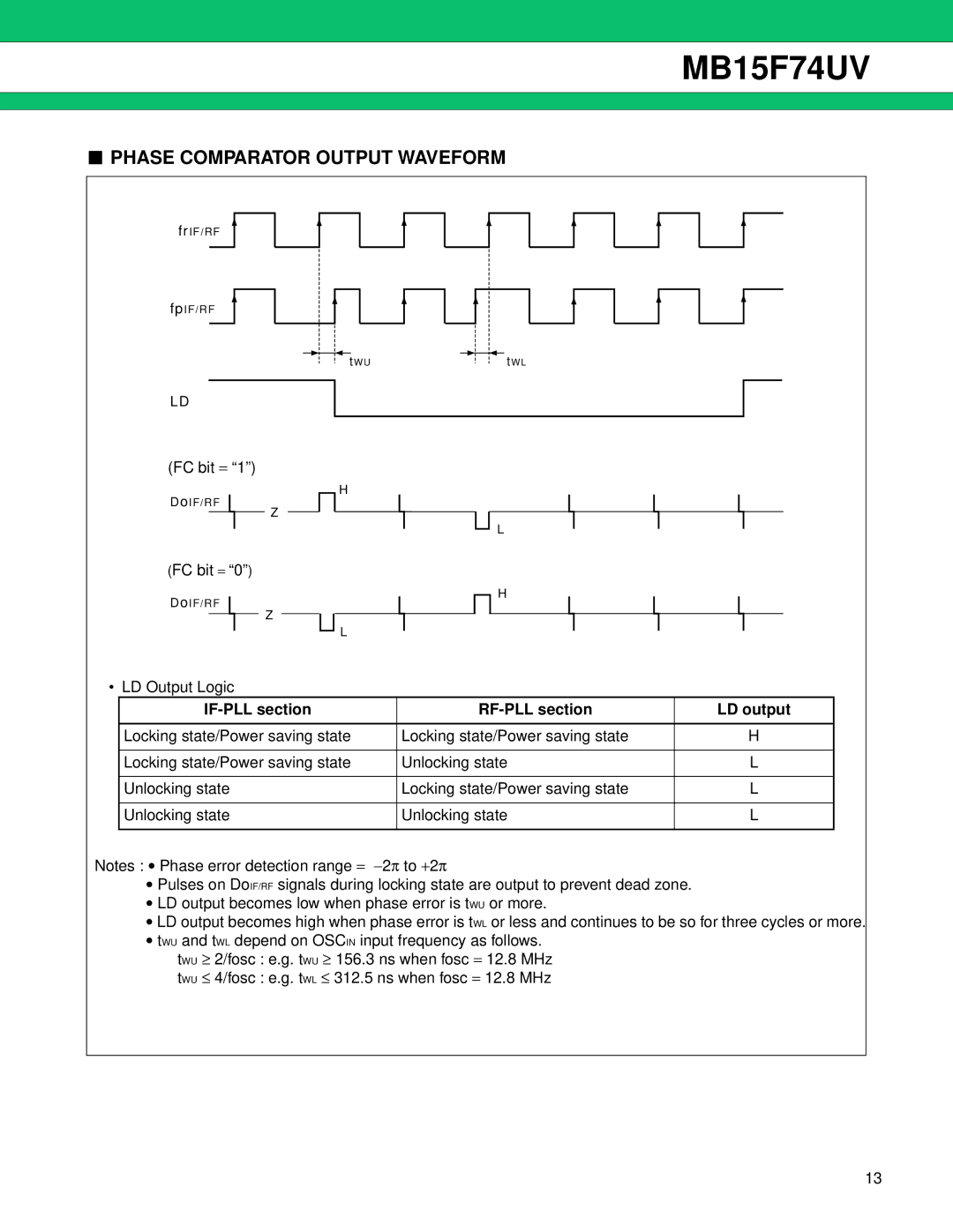
■PHASE COMPARATOR OUTPUT WAVEFORM
frIF/RF
fpIF/RF
tWU | tWL |
LD
(FC bit = “1”)
DoIF/RF
Z
(FC bit = “0” )
DoIF/RF
Z
H
L
L
H
• LD Output Logic
|
| LD output |
|
|
|
Locking state/Power saving state | Locking state/Power saving state | H |
|
|
|
Locking state/Power saving state | Unlocking state | L |
|
|
|
Unlocking state | Locking state/Power saving state | L |
|
|
|
Unlocking state | Unlocking state | L |
|
|
|
Notes : • Phase error detection range = −2π to +2π
•Pulses on DoIF/RF signals during locking state are output to prevent dead zone.
•LD output becomes low when phase error is tWU or more.
•LD output becomes high when phase error is tWL or less and continues to be so for three cycles or more.
•tWU and tWL depend on OSCIN input frequency as follows.
tWU ≥ 2/fosc : e.g. tWU ≥ 156.3 ns when fosc = 12.8 MHz
tWU ≤ 4/fosc : e.g. tWL ≤ 312.5 ns when fosc = 12.8 MHz
13