PS Engineering
PAV80
Installation and Operator’s Manual
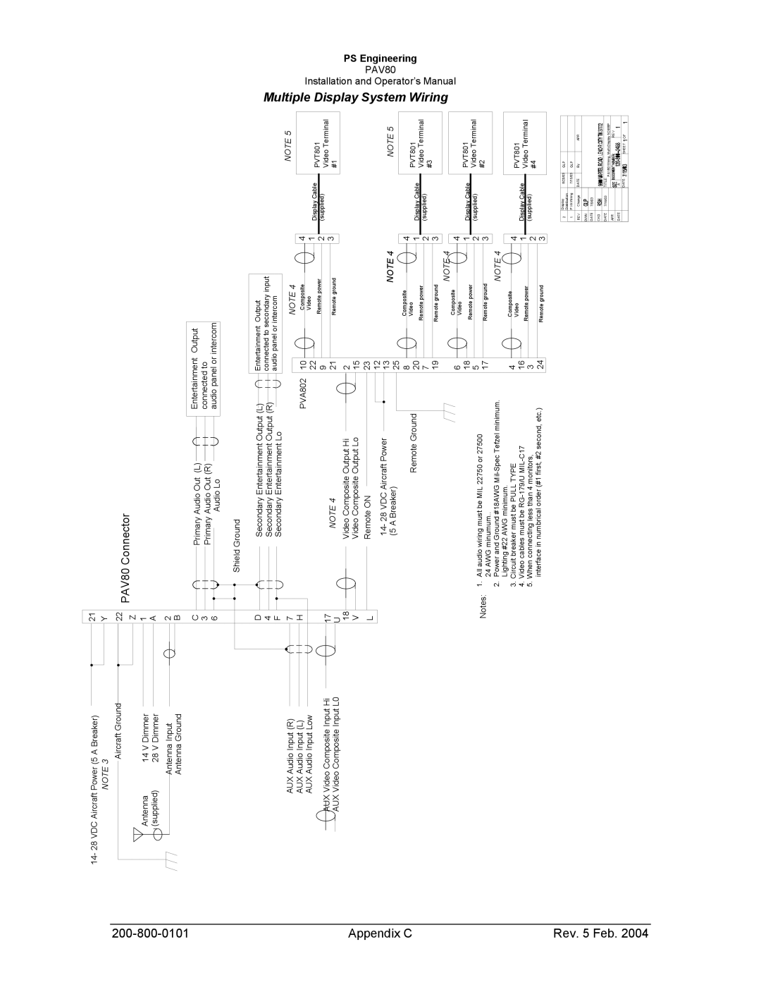
Multiple Display System Wiring
NOTE 5
PVT801TerminalVideo#1
CableDisplay(supplied)
NOTE 5
PVT801TerminalVideo#3
Display Cable(supplied)
PVT801Video Terminal#2
Display Cable(supplied)
PVT801Video Terminal#4
Display Cable(supplied)
|
|
| APR |
|
|
| REV |
| SHEET OF | |
GLP |
| GLP | By |
|
|
| PAV80Wiring, |
|
|
|
8/20/03 |
| 7/15/03 | DATE |
|
|
| TITLE: |
| A | DATE: |
Display | Distribution | PVAWiring | Change |
| 7/9/03 |
| 7/16/03 |
|
|
|
2 |
| 1 | REV | DWN | DATE | CKD | DATE | APR | DATE |
|
Output | intercom |
| to panelor |
Entertainment Output connected to secondary input audio panel or intercom
4123
NOTEVideoRemoteRemote 4Compositepowerground
1022921
| 4 1 2 3 |
| 4 1 2 3 | ||||||||||
|
|
|
|
|
|
|
|
|
|
|
|
| |
NOTE4 |
|
|
|
| Remoteground | NOTE4 |
|
|
|
| Remote ground | ||
Video Remotepower |
| Video Remote power | |||||||||||
|
|
| |||||||||||
| Composite |
|
|
| Composite |
|
| ||||||
|
|
|
|
|
|
|
|
|
|
|
|
|
|
|
|
|
|
|
|
|
|
|
|
|
|
|
|
|
|
|
|
|
|
|
|
|
|
|
|
|
|
2 15 23 12 13 25 8 20 7 19 | 6 18 5 17 | ||||||||||||
| 4 1 2 3 | |||||
|
|
|
|
|
| |
NOTE4 |
|
|
|
| Remote ground | |
| Video Remote power |
| ||||
|
| |||||
| Composite |
|
| |||
|
|
|
|
|
|
|
|
|
|
|
|
|
|
|
|
|
|
|
|
|
4 16 3 24 | ||||||
Entertainment connected audio |
| (L) | (R) |
|
|
PAV80Connector | Primary Audio Out | Primary Audio Out | Audio Lo | Shield Ground |
21 Y 22 Z 1 A 2 B | C 3 6 |
| ||
(L) | (R) |
|
| PVA802 |
|
|
|
|
|
|
|
| Remote Ground |
|
|
|
|
|
|
|
|
|
|
|
|
| |||||
|
|
|
|
|
|
|
|
|
|
| |||||
Secondary Entertainment Output | Secondary Entertainment Output | Secondary Entertainment Lo |
|
|
|
|
|
|
| wiringmustbeMIL22750or27500 |
| ||||
| Video Composite Output Hi Video Composite Output Lo |
|
| 14- 28 VDC Aircraft Power (5 A Breaker) |
| ||||||||||
NOTE4 | Remote ON |
| minumum.. | ||||||||||||
|
|
|
|
|
|
|
|
|
|
|
|
|
| Allaudio | 24AWG |
|
|
|
|
|
|
|
|
|
|
|
|
|
| 1. |
|
|
|
|
|
|
|
|
|
|
|
|
|
|
| Notes: | |
D 4 F 7 H | 17 U 18 V | L |
|
|
| ||||||||||
CircuitbreakermustbePULLTYPE | ||
2. | 3. | 4. 5. |
|
|
|
|
|
|
|
|
|
|
|
|
|
|
|
|
|
|
(5 A Breaker) | 3 AircraftGround | 14 V Dimmer | 28 V Dimmer | |||||
VDC Aircraft Power | NOTE | Antenna | (supplied) | |||||
14- 28 |
|
|
|
|
|
|
| |
Antenna Input Antenna Ground
|
|
|
|
|
|
|
|
|
|
|
|
|
|
| Video Composite Input Hi Video Composite Input L0 | ||
AUX Audio Input (R) AUX Audio Input (L) AUX Audio Input Low | |||||
|
|
| AUX AUX | ||
Appendix C | Rev. 5 Feb. 2004 |