6K32T, 6K32TRC specifications
The GarrettCom 6K32TRC and 6K32T are advanced, ruggedized network switches designed for mission-critical applications in challenging environments. These switches are notable for their reliability, versatility, and high performance, making them ideal for industries such as transportation, utilities, and industrial automation.One of the key features of the 6K32TRC and 6K32T is their robust construction. These switches are built to withstand extreme temperatures, humidity, and harsh conditions, ensuring continued operation even in the most demanding settings. With an operational temperature range of -40°C to +75°C, they can function effectively in various climates, making them perfect for outdoor or unconditioned environments.
Both models are equipped with Layer 2 and Layer 3 switching capabilities, offering flexibility for different networking needs. The 6K32T, for instance, is designed specifically for applications that require high-speed connectivity and data management. With support for various Ethernet protocols, these switches provide reliable data transmission and low latency, essential for real-time applications.
The 6K32TRC model features enhanced redundancy and failover capabilities. It supports a range of network topologies including ring, star, and mesh configurations, ensuring that network uptime is maximized even in the face of component failures. Redundant power supply options further guarantee continuous operation.
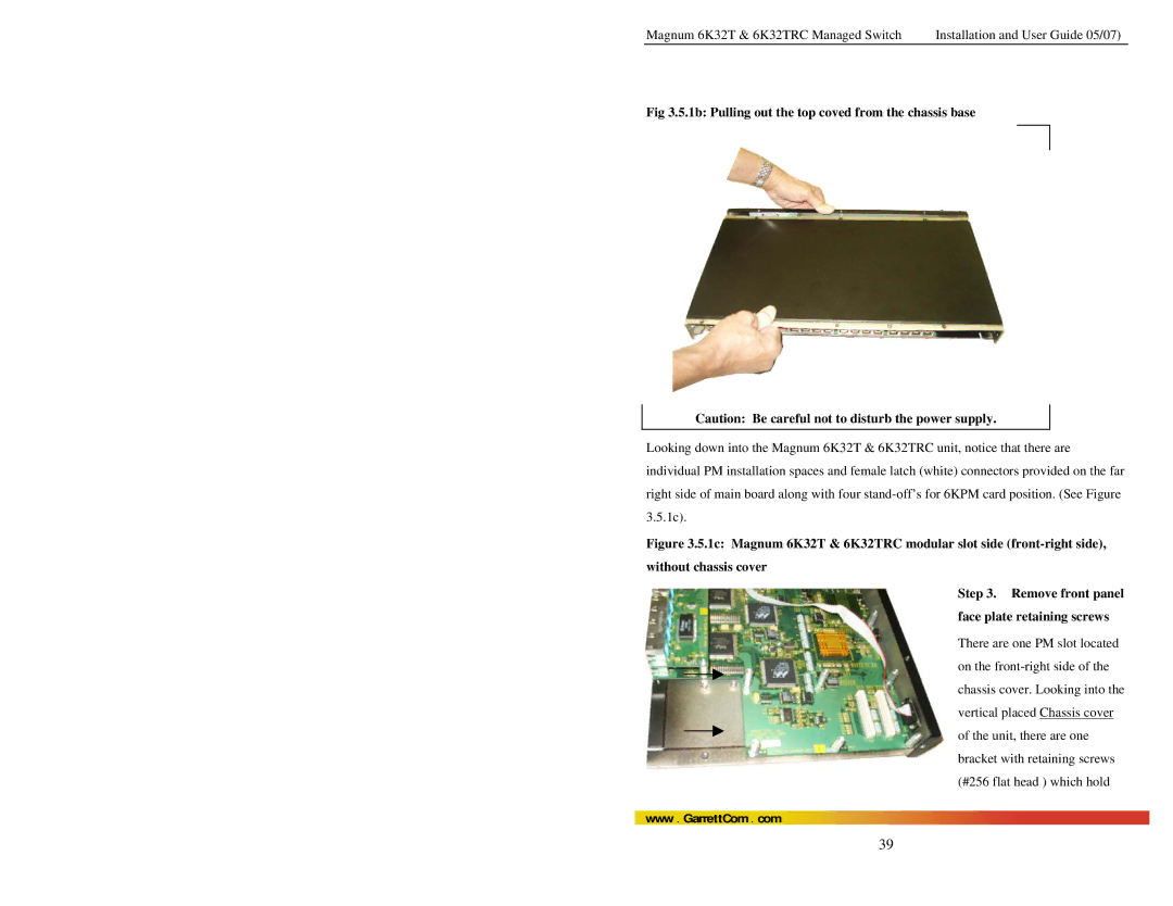
Scalability is another highlight of the GarrettCom 6K32 series. The switches are modular, allowing users to easily add or replace various interface cards to support additional network connections or management features without significant downtime.
Security is paramount in industrial settings, and the 6K32TRC and 6K32T adhere to modern cybersecurity standards. They include features such as access control lists (ACLs), Secure Shell (SSH) for encrypted management access, and VLAN tagging to enhance network security.
In terms of management, the switches support an array of protocols for easy integration and monitoring within existing networks. SNMP, RMON, and web-based management interfaces streamline the administrative process, ensuring that network managers can efficiently oversee their operations.
Overall, the GarrettCom 6K32TRC and 6K32T switches exemplify reliability and advanced technology. Their robust design, comprehensive feature set, and focus on security make them an excellent choice for organizations requiring resilient network solutions in challenging industrial environments.

