Installation Instructions

1 SHUT OFF MAIN WATER SUPPLY

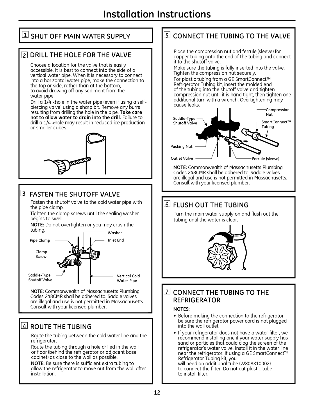
2DRILL THE HOLE FOR THE VALVE

Choose a location for the valve that is easily accessible. It is best to connect into the side of a vertical water pipe. When it is necessary to connect into a horizontal water pipe, make the connection to the top or side, rather than at the bottom,

to avoid drawing off any sediment from the water pipe.

Drill a 1/4ļ hole in the water pipe (even if using a self- piercing valve) using a sharp bit. Remove any burrs

5CONNECT THE TUBING TO THE VALVE

Place the compression nut and ferrule (sleeve) for copper tubing onto the end of the tubing and connect it to the shutoff valve.

Make sure the tubing is fully inserted into the valve. Tighten the compression nut securely.

For plastic tubing from a GE SmartConnect™ Refrigerator Tubing kit, insert the molded end of the tubing into the shutoff valve and tighten compression nut until it is hand tight, then tighten one additional turn with a wrench. Overtightening may cause leaks.

resulting from drilling the hole in the pipe. Take care not to allow water to drain into the drill. Failure to drill a 1/4ļ hole may result in reduced ice production or smaller cubes.

Saddle-Type

Shutoff Valve

Packing Nut

Outlet Valve

Compression

Nut

SmartConnect™

Tubing

Ferrule (sleeve)

3FASTEN THE SHUTOFF VALVE

Fasten the shutoff valve to the cold water pipe with the pipe clamp.

Tighten the clamp screws until the sealing washer begins to swell.

NOTE: Do not overtighten or you may crush the

tubing.

Washer


Pipe Clamp

Inlet End

Clamp


Screw


Saddle-Type

Vertical Cold

Shutoff Valve

Water Pipe

NOTE: Commonwealth of Massachusetts Plumbing Codes 248CMR shall be adhered to. Saddle valves are illegal and use is not permitted in Massachusetts. Consult with your licensed plumber.

4ROUTE THE TUBING

Route the tubing between the cold water line and the refrigerator.

Route the tubing through a hole drilled in the wall or floor (behind the refrigerator or adjacent base cabinet) as close to the wall as possible.

NOTE: Be sure there is sufficient extra tubing to allow the refrigerator to move out from the wall after installation.

NOTE: Commonwealth of Massachusetts Plumbing Codes 248CMR shall be adhered to. Saddle valves are illegal and use is not permitted in Massachusetts. Consult with your licensed plumber.

6FLUSH OUT THE TUBING

Turn the main water supply on and flush out the tubing until the water is clear.

7CONNECT THE TUBING TO THE REFRIGERATOR

NOTES:

Before making the connection to the refrigerator, be sure the refrigerator power cord is not plugged into the wall outlet.

If your refrigerator does not have a water filter, we recommend installing one if your water supply has sand or particles that could clog the screen of the refrigerator’s water valve. Install it in the water line near the refrigerator. If using a GE SmartConnect™ Refrigerator Tubing kit, you

will need an additional tube (WX08X10002) to connect the filter. Do not cut plastic tube to install filter.

12

Page 12
Image 12
GE 20 Shut OFF Main Water Supply Drill the Hole for the Valve, Connect the Tubing to the Valve, Fasten the Shutoff Valve

22, 20 specifications

The GE 20,22 series engines represent a significant evolution in aviation technology, embodying advancements that enhance efficiency, reliability, and environmental sustainability. As part of General Electric's commitment to innovation in aerospace propulsion, these engines are designed to meet the rigorous demands of modern commercial aviation while minimizing their environmental footprint.

One of the main features of the GE 20,22 engines is their high bypass ratio, which plays an integral role in achieving improved fuel efficiency. By maximizing the amount of air bypassing the engine core, these engines produce more thrust without a proportional increase in fuel consumption. This characteristic makes them ideal for long-haul operations, effectively reducing operating costs for airlines.

The engines also incorporate advanced materials and manufacturing techniques. The use of lightweight composite materials in fan blades and cases contributes to overall weight reduction, enhancing performance without sacrificing durability. Additionally, the integration of advanced ceramic matrix composites (CMCs) in critical components allows for higher operating temperatures, thereby increasing efficiency and reducing emissions.

Technologically, the GE 20,22 series engines are equipped with state-of-the-art digital control systems. These systems provide precise monitoring and adjustments during operation, leading to optimal performance and reduced maintenance requirements. The implementation of real-time data analytics allows for predictive maintenance, enabling operators to anticipate issues before they arise, thereby improving overall reliability.

Noise reduction is another critical characteristic of the GE 20,22 engines. They feature designs and technologies that significantly diminish noise levels during operation, addressing the growing concerns of communities around airports. This commitment to reducing noise, in conjunction with lower emissions, aligns with global efforts to create a more sustainable aviation industry.

Finally, the GE 20,22 engines are compatible with alternative fuels, showcasing General Electric’s forward-thinking approach to sustainability. As the aviation sector moves towards greener solutions, these engines are positioned to use biofuels and synthetic fuels, further decreasing their ecological impact.

In conclusion, the GE 20,22 series engines embody the latest in aerospace technology with their efficiency, reduced emissions, advanced materials, and noise reduction capabilities. Their design not only meets the needs of today’s airlines but also contributes to the industry's path towards a more sustainable future.