geappliances.com
Remote Thermostat Control
In some installations, control of the operation of the unit at a location remote from the unit itself may be desired. A unit mounted high in the wall or over a door, for instance, where the
Important Notes: Remote thermostat wiring should not be run through wall case. Thermostat wiring should exit the wall below the unit and enter the unit between room cabinet and chassis. Wire molding may be used to hide thermostat wiring. If a
All Zoneline 4100 and 6100 Series units are adaptable to Class 2 remote
The controls on the unit are not functional when the remote control function is used.
Resistance Heat Models
The Zoneline 4100 resistance heat units may be connected to a
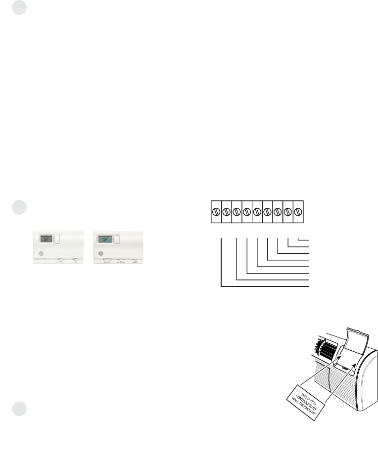
RAK164D1 — | RAK164P1 — |
a | a |
digital thermostat | programmable |
requiring five | thermostat |
connection wires. | requiring five |
| connection wires. |
The remote
Please see page 55 for installation recommendations for the remote thermostat wiring.
Compatibility of other thermostats considered for use with GE Zoneline units is the responsibility of the customer. The control voltage on the remote control conductors is 24 volts AC. The AC voltage may not be compatible with some
The fan speed for the 4100 Series in remote thermostat operation is selected by the connection of the fan wire from the thermostat to either the HIGH or LOW terminal on the unit. See the sketch of the unit terminals below for the location of the HIGH and LOW
Freeze Sentinel™ and Heat Sentinal remain operational if the unit is connected to a remote thermostat. The unit may be connected to a Central Desk Control (CDC) system and controlled with a remote thermostat when the CDC system has the unit in operation. See page 14 for additional information on the CDC system.
Unit temperature limiting settings are not functional when unit is connected to a remote thermostat.
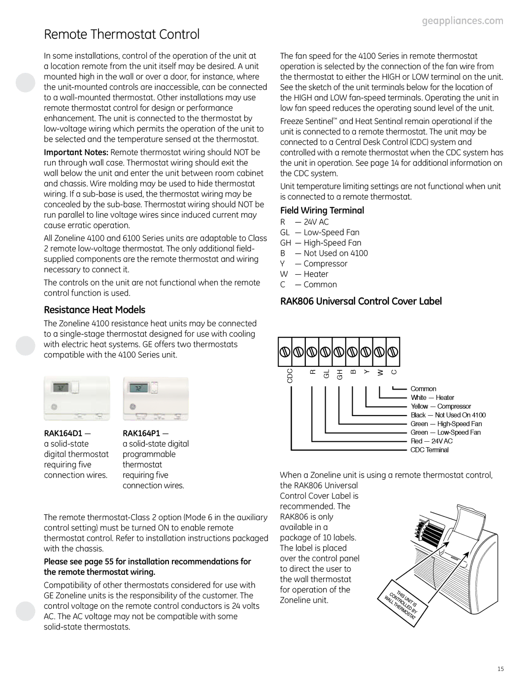
Field Wiring Terminal
R — 24V AC
GL —
GH —
B— Not Used on 4100
Y— Compressor
W— Heater
C— Common
RAK806 Universal Control Cover Label
CDC | R GL GH B Y W C |
Common
White — Heater
Yellow — Compressor
Black — Not Used On 4100
Green —
Green —
Red — 24V AC
CDC Terminal
When a Zoneline unit is using a remote thermostat control, the RAK806 Universal
Control Cover Label is recommended. The
RAK806 is only available in a package of 10 labels.
The label is placed over the control panel to direct the user to
the wall thermostat for operation of the Zoneline unit.
15